
The prevalence of impacted cuspids is approximately one to two percent of the population. For those individuals with impacted cuspids who seek orthodontic treatment, they can expect more complicated mechanics and increased treatment time. There is a similar prevalence of cases with peg lateral incisors. These situations also present challenges for the orthodontist and the restorative dentist alike. One solution for peg laterals with poor prognosis can be substitution of the cuspids into the lateral incisor position. With proper management, a very acceptable result is often possible. Of course, CL II management in non-growing patients presents challenges in treatment as well, with a need to consider upper bicuspid extraction or surgical correction of a skeletal discrepancy to achieve an acceptable result. This case report presents an interesting patient presentation that combines all of these considerations.
Case Study
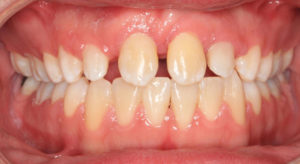
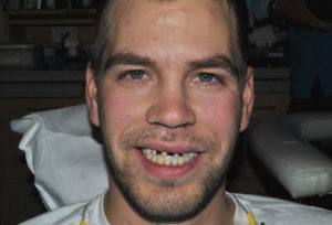
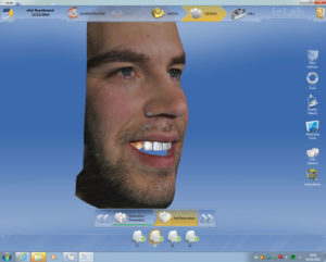
This patient presented in January 2010 to the orthodontist with a chief concern that the “cuspids need to be brought down” and that he wanted to address his front teeth that had been traumatized in a hockey accident three years prior. Diagnostic records were obtained in March; five days prior to the records, he fell and traumatized 22. Figures 1 and 2 shows patient’s full smile and retracted anterior view.


Upon initial examination, our findings showed an increased vertical jaw relationship. This was due to the posterior rotation of the mandible and contributed to the open bite tendency and a class II malocclusion. His open bite was compounded by factor of his central incisors as seen in Figure 3.

Figure 3 shows impacted cuspids 13, 23, pegged lateral incisors, supernumerary tooth between 22-24 as well as severe maxillary crowding and moderate mandibular arch crowding.
Treatment Plan
Due to the complexity and challenges dentally presented with this case, there are a number of treatment options that could have been considered. The reality of this case was that after orthodontics was completed, the case was presented, and the patient would only be available for three days. The treatment would need to be completed by then. This really simplified our restorative treatment plan options. It was decided that our only choice, given time constraints, was using Sirona InLab Smile Design software in combination with CEREC (Sirona) CAD/CAM design and in-house milling.
The orthodontist had already decided that restoring 11 and 21 was not feasible due to the poor restorative prognosis and were planned for extraction. As the impacted cuspids were approaching the central incisors, the cuspids were erupted in the position of the central incisors post extraction. The pegged lateral incisors were maintained to assist with orthodontic anchorage. Figures 4 and 5 show the final orthodontic position with 13, 23 in the position of (formerly extracted) 11 and 21.

As you can see, there were tremendous restorative challenges due to asymmetrical proximal spacing, tooth size discrepancies, and asymmetrical anterior dental midlines. Due to severe time limitations, we didn’t have the ability to do any pre-preparation wax-ups or diagnostic aesthetic evaluations.
Restorative Phase
The cuspids and peg lateral incisors were prepared for CAD all ceramic crowns with the supra gingival margins on enamel. Figure 6 shows prepared teeth and uneven proximal spacing.
After the preparations were complete, it was necessary to take a normal digital photograph of the patient smiling to be imported to our Sirona Inlab design software. Note that the patient’s facial midline was not coincident with his mandibular dental midline as seen in Figure 7.

A digital impression using Sirona’s Omni cam was taken. As you can see a colour digital 3D rendering of the patient’s prepared maxilla, mandible and bite was captured into the software. Figures 8 and 9 show occlusal and anterior scanned images from CEREC’s OmniCAM.
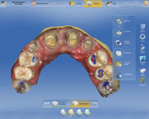

Figure 8 shows preparations from the occlusal view as well as occlusal contact points. As seen in Figure 9, an approximated final incisal and maxillary midline position was roughly drawn with pencil and captured by the Omni cam on the facial surfaces of 31 and 41. This was to help confirm our smile design is accurate.
Next, preparation margins were identified easily with CEREC’s auto margination feature as shown in Figure 10.

The next step in our lab component with CEREC software is to upload the full face smile photo that we took after preparation of the teeth, and transfer the intercanthi width (far corner of eye to corner of other eye in mm) to calibrate the photo to the digital impression as shown in Figures 11 and 12.


The full integration of the digital facial photo and digital impression is shown in Figure 13. The digital impression is guided into correct position by utilizing the software tools as seen in Figure 13.
Once the integration was completed, the next step is an initial proposal by the CEREC software for four anterior crowns, 12 to 22. There are many design tools that are used to adjust the shape, size, length and anatomic form of the restorations. These tools are very intuitive and as one becomes more experienced with design, their actions become second nature. Figure 14 shows the final design of the crowns to be superimposed and manipulated on the full facial smile design photo of the patient (Fig. 14).

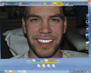
This photo can be grabbed and rotated three dimensionally in any direction to illustrate to the patient chairside (and the dentist) exactly what the 3D crown proposal setup is (Figs. 15 and 16).

Each restoration can then be altered so that the midlines are straight and coincident to the facial midlines and the incisal length positioning can follow the lower lip line. Being able to visualize the final proposal in his own smile was invaluable to the patient experience. Once the patient viewed this proposal, it was accepted and the crowns were milled.
Figures 17 and 18 show the transparent restorations over the preparations. As one can see, the orthodontic asymmetries of tooth positioning was corrected in our CEREC crown design. This would not have been possible without the Smile Design software.


The CAD/CAM ceramic block of choice was Vita’s Tri-Lux Forte. This block contains four layers of feldspathic porcelain built into the block. This mimics the labour intensive layering techniques that the lab artists (technicians) do for ultimate aesthetics. Figure 19 shows the stratified layers of the block, which can be raised or lowered to alter the opacity and translucency of the milled crown.

Figure 20 shows the untreated freshly milled crowns. Also visible is the natural chroma progression from gingival to incisal that is built into this block. Some incisal variations and texture characterizations were cut into the porcelain using a finishing diamond bur. The patient verified the shade and contours (this time intraorally) and the crowns were treated with surface glaze, fired in the VITA PM oven and polished for insertion. Figure 21 shows the completed restorations after cementation (with Ivoclar’s Multi-link and a self-etch technique using a yellow shaded cement, which warmed the overall value of the restorations), and final polishing of the margins.


Digital Timeline
As you can recall, the patient presented for the first time from the orthodontist. At that time, we took facial photos, prepped, and designed the crowns in a matter of two hours. The crowns were milled the next day for try-in, finalization, and insertion. This took a total of three hours. The grand total for this improbable task was completed start to finish in five hours, which included combined chair and lab time. This was an incredible result for our patient and an incredibly rewarding experience for the dentist. The true value as a restorative dentist was shown by our patient’s emotional reaction when seeing his new smile. This is the true power and versatility of digital dentistry.
Conclusion
Final post-operative check of the restorations were done several months later when the patient returned to town for a visit , as shown in Figures 22, 23 and 24. Tissue response and healing were uneventful. This case was only possible given our timeline with the use of CAD/CAM dentistry and is a tremendous adjunct to our restorative practice.


About the Authors
Amarjit Rihal obtained his DMD degree from the University of Manitoba, Faculty of Dentistry, in 1995. His professional interest has involved all aspects of implant and CAD/CAM dentistry. He has additional training in both hard and soft tissue grafting as well as placing and restoring implants. In addition to implantology, Dr. Rihal has acquired expertise in CAD/CAM based prosthetic dentistry, involving numerous CAD systems and materials. Utilizing his CEREC ac and InLab system he has designed over 2000 restorations. He presently is a partner in a large group practice in Winnipeg, MB and serves on the boards of the Manitoba Dental Association and the National Dental Examination Board. He has newly be elected to the Commission on Dental Accreditation of Canada. He was also a part time clinical instructor at the University of Manitoba Faculty of Dentistry and is a fellow of the Pierre Fauchard Academy and International College of Dentist.
Tim Dumore has practiced orthodontics in Winnipeg since graduating from the orthodontic residency at University of California, San Francisco in 1998. He has a special interest in interdisciplinary treatment and is co-director of the Winnipeg Progressive Dental Study Club, a chapter of the Seattle Study Club. His practice places a significant focus on technology, with early adoption of digital radiographs and CBCT, intra-oral scanning, and 3D printing. He has been a part-time clinical instructor at the University of Manitoba Faculty of Dentistry Graduate Orthodontic program for sixteen years. In 2013, he was invited to be a member in the Schulman Study Group.
Les Rykiss maintains his private practice in Winnipeg, MB. He is a graduate of the University of Manitoba as well as a graduate and Mentor at the Nash Institute for Dental Learning in Charlotte, N.C. He has his Fellowship with the International Academy for Dental Facial Esthetics, an associate Fellowship from the World Clinical Laser Institute, and is a member of the ASDA and CAED. He teaches, lectures, and writes articles on restorative, cosmetic dentistry, and hard and soft tissue laser use.
RELATED ARTICLE: 3D Digital Smile Treatment Plan: What are Advantages for Patient and Dentist?


