
Abstract
The success of dental implant procedures is dependent on many factors. Overall medical status and health, and economic considerations can be limiting factors in determining which of our patients are appropriate candidates. Additionally, the time required for some implant treatments, and the need to perform bone grafting and augmentative procedures in a staged manner often deter patients from proceeding with implant borne prosthetic rehabilitation.
Recently, numerous alternatives have been introduced and developed to circumvent anatomic limitations and the need for grafting or nerve repositioning procedures and their attendant economic costs, treatment times and morbidities. The use of shorter implants, ridge splitting/ridge expansion/ and densification surgeries using specially designed burs or piezotomes, and angled prosthetic components allowing for angulated or tilted implant placement, in deficient areas are challenging traditional dogma. Success rates utilizing angulated implants are similar to those of traditional axial placements, and marginal bone levels appear to maintain similarly to axial placements. Maxillary sinus grafting procedures can be associated with increased treatment times, and do have potential complications such as Schneiderian membrane perforation and infection associated with them. A case report is presented of an eighty three year old female who was successfully treated with an implant borne fixed bridge, placing the distal implant in a tilted manner to avoid a significantly pneumatized sinus, and increasing the A-P spread to minimize the size of the distal cantilever. The treatment planning, surgical and prosthetic steps undertaken in this case are described, as well as the pros and cons of providing this type of treatment.
INTRODUCTION
Implant dentistry has proven to be a successful and reliable modality and addition to the Dentist’s armamentarium.1 Prosthetic rehabilitation with implants is becoming a well-established mode of treatment. The placement and maintenance of a functional and esthetic implant supported restoration can be a clinical challenge. Meticulous pre-planning is necessary with considerations of the anatomic structures and mesial/distal apical/coronal, and buccal/palatal dimensions, as well as occlusion in the proposed implant sites. Good quality and quantity of bone for implant placements are very important considerations for long term success. Patients with severe resorption of alveolar bone often require prior additional surgical procedures in the form of bone augmentation and sinus lift procedures for a successful outcome.
Traditionally, it is well established that the masticatory forces must be directed along the long axis of the implant to increase the longevity of the implant restoration and reduce the amount of bone resorption over time. Implants placed at positions off the vertical axis have been referred to as “tilted implants” or “off-axis fixtures.” These may be placed to avoid various anatomical structures or to eliminate the need for bone grafting and nerve repositioning procedures.2
Recently, numerous alternatives have been introduced and developed to circumvent anatomic limitations and the need for grafting or nerve repositioning procedures and their attendant economic costs, treatment times and morbidities. Short implants, ridge splitting/expansion/densification surgeries using specially designed burs, and angled prosthetic components allowing for angulated or tilted implant placement, in deficient areas are challenging traditional dogma. Success rates utilizing angulated implants are similar to those of traditional axial placements, and marginal bone levels appear to maintain similarly to axial placements.3-8 Maxillary sinus grafting procedures can be associated with increased treatment times, and do have potential complications. Despite the reliability and predictability of these procedures, sinus floor augmentation has not been complication free. The most common complications include tearing of the Scheiderian membrane, with a reported rate of 7%-56%, graft failure and infection/sinusitis.9,10
CASE REPORT
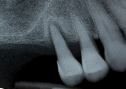
The patient is an eighty-three years old female who presented requesting a solution to her missing and loose teeth on her maxillary right side. Her medical health is non-contributory, and her high blood pressure is being controlled with medications. Her TMJ’s are comfortable, with no pain, clicking, deviations or limited range of movement on opening or closure. She has generalized moderate periodontal disease. A periapical radiograph (Fig. 1) reveals teeth #15 and #14 have advanced bone loss, and the maxillary sinus is significantly pneumatized, with minimal bone present on the sinus floor, and teeth 16, 17, 18 are absent. Various treatment options were reviewed with the patient including: extraction of teeth #14, #15 and replacement with an RPD, or extracting the premolars and performing a sinus grafting/augmentation procedure in order to place four implants with fixed implant supported crowns and restore the maxillary #17- #14 quadrant, or place two implants with a fixed bridge prosthesis from #16 to #14 (with sinus grafting being performed), or place a sole implant in the #15 sites for a ‘Locator’ stud type of overdenture support for an RPD. The patient reports having worn an RPD in the past, and being very unhappy with it. She is interested in a fixed solution involving implant support, but given her age, and financial situation, she is not interested in having sinus grafting performed. The possibility of placing an angulated implant in the #15 site to avoid the need for sinus grafting was discussed, and the patient was interested in exploring this treatment option. The need for a CBCT scan and a surgical stent’s fabrication was explained to the patient.
Fig. 1
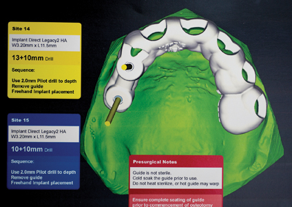
A week later, #15 was extracted using local anesthetic, and the extraction site was carefully cleaned of any granulation tissue, and the site allowed to heal, and any residual infection to clear up, in anticipation of possible implant therapy. The patient was referred for a CBCT scan and the results evaluated by an Oral Radiologist. It was determined that there was sufficient bone for an implant supported three-unit bridge, replacing Teeth #16,15,14, if the distal abutment was angulated. (Fig. 2) The patient returned for a post-op and final consultation and accepted this treatment option after the risks/benefits and anticipated time frame for the case was reviewed, and any questions answered. The Oral Radiologist and imaging center technicians, and author collaborated to fabricate a surgical stent to assist in the placement of the distally angulated #15 implant, which was fabricated ahead of the implant placement appointment. (Fig. 3) It was designed to fit over the #13 and other anterior teeth, which would provide the necessary support and stabilization (the first premolar would need to be extracted first to allow the surgical stent to be seated). The treatment plan developed was for a screw retained fixed bridge, with #15 being distally angled to increase the A-P spread to minimize the distal cantilever at the #16 site.
Fig. 2
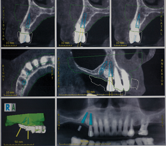
Fig. 3
Six weeks after the #15 was extracted, the implant placement appointment was scheduled. Local anesthetic via buccal and palatal infiltration was administered, and tooth #14 was extracted atraumatically, using periotomes and Physics Forceps. The extraction socket was carefully degranulated with a curette and the buccal plate was evaluated and found to be intact. The surgical guide was now introduced and seated in place. (Figs. 4-5) Osteotomies were prepared in the #14, #15 sites using a series of graduated burs, with copious cooled saline irrigation, to prepare for the planned diameter and length of the implants to be placed. The osteotomies were slightly undersized to preserve bone and increase the insertion torque values obtainable. One limitation with the use of surgical guides involving distal angulations is the difficulty for the patient to open sufficiently to allow access for the burs and handpiece. The patient has a small mouth, and after the pilot burs in the osteotomy series, couldn’t tolerate the surgical guide. The final steps in preparing the osteotomies, and inserting the implants (Legacy 3 Implant Direct) were performed free-hand (accounting for the slight discrepancy between the CBCT plan and actual placement positions). The #15 site was found to have softer bone than anticipated, and as a result a slightly longer implant was selected to engage more bone, and achieve a higher insertion torque. (Fig. 6) Ideally, there would be slightly greater distance between the apices of the two implants. Both implants were found to have good insertion torque and 3.0 mm. healing abutments were placed. (Fig. 7) No Ostell reading of the insertion torque was taken. No grafting of the buccal wall of #14 was required, as the gap was less than 1mm, and would be expected to routinely fill in with native bone.11 Post-operative instructions, antibiotics and pain medications were prescribed. The patient was seen at day two, one week and two weeks after the surgery and healing and comfort were found to be good. The sites were allowed to heal for four months, (Fig. 8) after which a new set of impressions and custom impression trays were fabricated.
Fig 4

Fig. 5

Fig. 6

Fig. 7
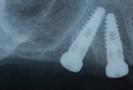
Fig. 8
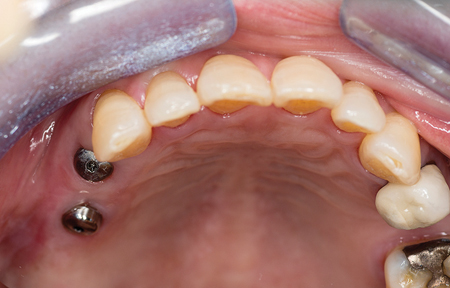
A custom tray with open tray transfer abutments was used to obtain the final polyvinyl siloxane impression. (Figs. 9-13) A radiograph was taken to verify complete seating of the transfer abutments. CR bite records, a face bow transfer and opposing arch impressions, and tooth shade selections were taken. The lab fabricated a Duraly stent to verify the accuracy of the stone cast model, prior to proceeding with the final bridge’s fabrication. (Fig. 14) The patient was reappointed a few days after the impressions were taken, the healing abutments were removed and the Duralay stent was used to seat the #15 Multi-abutment and #14 abutment in the mouth, and the stone cast’s accuracy was confirmed, as the Duralay stent’s fit in the mouth was the same as seen on the stone casts. (Fig. 15) The healing abutments were replaced after flushing the implant sites with a diluted hydrogen peroxide and water solution and drying the implant channels with endo paper points. Two weeks later, the patient was seen for the delivery of her fixed prosthesis. The healing abutments were removed, and the gingiva appeared to be healthy. A dilute hydrogen peroxide solution in a Monoject disposable syringe was used to irrigate the implant sites, and dried, prior to abutment placement. No local anesthetic was required. A second Duralay stent and small handle were fabricated by the lab (Figs. 16-17) to hold the distally angled #15 multi-abutment seated in the correct orientation till the multi-abutment screw was secured at the prescribed 15 NCm. torque. (Figs. 18-19) The lab fabricated prosthesis (Figs. 20-21) was seated, and secured with abutment screws at 25 NCm. torque. (Fig. 22) A radiograph was taken to ensure complete seating of the prosthetic components. The screw channels on #14, #15 were sealed with Teflon plumber’s tape (Fig. 23) and a shade matched composite resin was light cured to seal the access (Fig. 24).
Fig 9

Fig. 10

Fig. 11

Fig. 12

Fig. 13
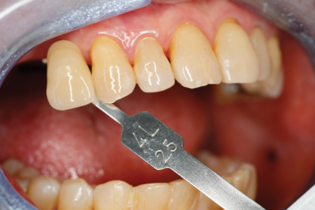
Fig. 14

Fig. 15
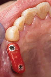
Fig. 16
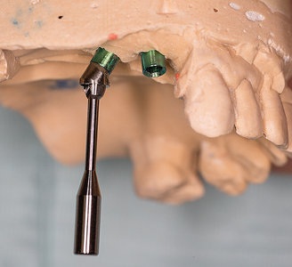
Fig. 17

#15 Multi-abutment.
Fig. 18
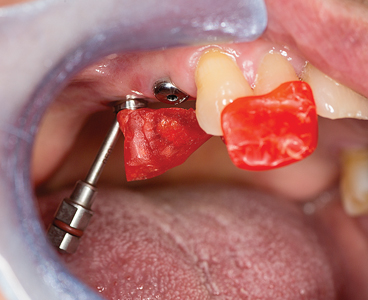
Fig. 19
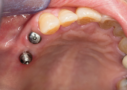
Fig. 20
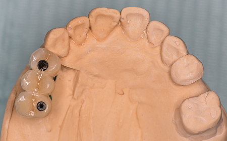
Fig. 21

(intaglio view).
Fig. 22
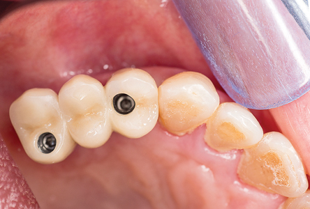
Fig. 23
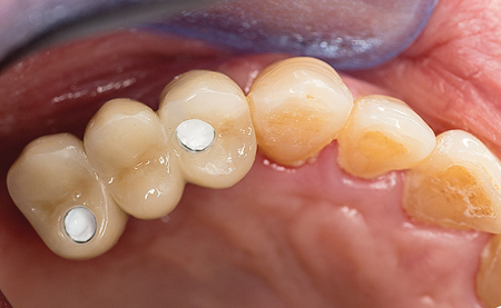
Fig. 24

Occlusion was verified and adjusted with ultra- fine diamonds using copious water spray, as required. Post-operative instructions in home care, soft diet for four weeks and bridge flossing were reviewed. The patient was seen the following week and two weeks later for follow up. The patient was very pleased with the esthetics, (Fig. 25) comfort and function achieved. To date, the prosthesis has been in function for three years. Fig. 26)
Fig. 25
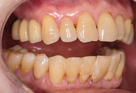
Fig. 26

DISCUSSION
Dr. Paulo Malo in 1993 advocated angulated placement of implants in edentulous cases with advanced resorption and named this concept as “All on four” in which two vertical implants were placed in the anterior region and two implants in the posterior region were placed at an angulation of 35-40 degrees. Since then, several clinicians and researchers have reported use of angulated implants with varying degrees of success over a period of time but there is no consensus about the routine use of angulated implants for rehabilitation of patients with severely resorbed alveolar ridges. There are multiple advantages to the angulated placement of implants. These include being able to utilize longer implants and increasing the percentage of bone to implant contact, and eliminating the need for bone grafting or sinus lifting. Being able to use longer implants also increases the primary stability able to be achieved. Angulated implant placement allows the clinician to avoid anatomic structures such as a pneumatized maxillary sinus.12,13,14 Distally tilted implants induced better loading transmission than vertical implants.15,16,17 Angulated abutment placement can allow for conservative implant treatment in an otherwise medically compromised patient.18 There is a biomechanical advantage in using tilted distal implants rather than distal cantilever units, and the length of the cantilever can be reduced, which helps minimize strain at the abutment implant interface.19,20 The literature also demonstrates that the wider the spread of the implants in the arch along the alveolar crest is, the more beneficial the load distribution. The improved support gained when implants are spread more posteriorly has been reported.2 Success rates utilizing angulated implants are similar to those of traditional axial placements, and marginal bone levels appear to maintain similarly to axial placements.21 Krekmanov et al. studied tilting of posterior implants for improved prosthesis support in 47 patients and found that there were no implant failures in mandible while cumulative success rates in the maxilla at five years were 98% for tilted implants and 93% for non-tilted implants.7
Angled abutments can be used to restore dental implants placed in a non-parallel fashion. The longer-term effects of abutment angulation on bone strain is unknown. The greatest strain is found on the cancellous bone, adjacent to the most apical microthreads on the palatal side of the implant where tensile forces are created. The same strain distributionis observed around both the straight and angled abutments. Most of the deformation occurs in the cancellous bone and ranges between 1000 and 3500 microstrain. Small areas of cancellous bone experience strain above the physiologic limit (4000 microstrain). Most of the strain produced on the cancellous and cortical bone is within the range that has been reported to increase bone mass and mineralization.22,25
Ongoing research is attempting to determine the safest placement distance between a tilted implant and adjacent straight implant. A trigonometry ratio was developed to estimate a two-dimensional safe distance between a tilted implant and an adjacent vertical implant. The distance or length between the fixtures can be determined by multiplying the known length of each implant by a constant derived from the sin of the insertion angle. If inter-implant distance is increased, load distribution will be better.26 Malo et al suggest placement of angulated implants in cases demonstrating D3 or greater bone density, as per Dr. Misch’s classification.1 The placement of implants in an angulated fashion requires proper interpretation and treatment planning of the CT scan, and inter-implant angulations should be confined to a single three-dimensional plane to simplify prosthetic restoration. Single tooth restorations and cantilever bridges on angulated implants should be avoided, and the aim should be to splint the implants, to avoid exceeding the bone stresses/strain limits at the implant abutment interfaces. Inclinations of the implants lead to increased force levels at the implant-bone and implant-abutment-interfaces.27 Therefore, extreme angulations greater than 30 degrees should be avoided.28
There are disadvantages posed in the placement of angulated implants. As these techniques are relatively new, no long-term studies are available, although the short and medium term results appear promising. Oftentimes, the patients are medically compromised and/or geriatric, and present with poly-pharmaceutical usage and medical conditions such as diabetes mellitus and heart disease, which can affect normal bone metabolism and healing and osseointegration. Therefore communication/coordination with the patient’s medical doctor is often indicated. The use of a computer generated surgical guide is required to place the implant in the correct position. Preventing the osteotomy site from overheating can be a challenge when using surgical guides, as the cooling saline may not be able to reach the deepest portions of the osteotomy being created. Step-wise development of the osteotomy with increasingly larger graduated bur diameters, used in a short in/out advancing fashion to final depth may help prevent overheating in the osteotomy preparation. Distal placement of an implant through the surgical guide can be a challenge in patients with small mouths or with limited abilities to open wide. The development of various extra-oral computer assisted procedures such as the Navident (Claro Nav) or X-Guide (Nobel Biocare) may help obviate this challenge. The procedure is technique sensitive and slight alterations in the implant’s placement position can affect the ability of the final prosthesis to accurately fit (especially a concern in cases where the prosthesis is fabricated ahead of time, and delivered at the time of implant surgery. The use of an open tray impression system with traditional impression materials can be challenging to seat, and remove in cases involving angulated implants. It is important to find the impression pins prior to the material setting to facilitate easier removal. Mira-tray (Hager Worldwide Inc.) and similar products assist in locating the impression pins during the impression’s setting, or the use of orthodontic tray wax or Teflon tape to block the opening on the top of the impression pins can be employed.
In cases involving an atrophic maxilla, traditional implant placement isn’t possible without undergoing invasive procedures like bone augmentation and/or sinus lift procedures. Several types of complications may occur during and after the sinus elevation procedure like Schneiderian membrane perforation, nose bleeding, post-operative pain and swelling. The additional burden of an extra surgery and increased cost if enough bone isn’t available to carry out sinus lift and implant placement at same appointment can deter many patients from proceeding with implant therapy.
Bone grafting, while achievable, is dependent on many factors like the type of bone graft used (autogenous, alloplastic or xenograft), host response, age of patient, and surgical skill level of the clinician, and various complications associated with grafting procedures, such as infection and flap opening and premature exposure the graft can occur. For many patients seeking quicker solutions, the additional time spent while graft materials mature and are converted is problematic. Bone tolerates forces more favorably when they are directed vertically. The angulated implants direct the forces at an angle and thus are associated with higher forces acting on implant bone interface during axial loading. However; it has been shown that tilting of posterior implants improves prosthesis support.7 In one meta-analysis, no differences were found in success rate between tilted and axial implant.29 This suggests that splinted tilted implants can be placed with similarly high success rates as that of axial implants. Considering all these things, placement of an angulated implant avoiding both invasive procedures like sinus lift and bone augmentation procedure is a viable treatment option.30
Further long term clinical and histopathological studies are necessary to confirm the use of angulated implant placement in routine practice. However, this procedure is a viable concept in the short and medium term. While short-term studies show no difference in amount of bone loss around axial and angulated implants,31 data available is not sufficient to predict long-term success. Therefore, longer term clinical and histopathological studies are necessary determine if this modality will have a place in routine practice.
CONCLUSION
The case presented was an alternative mode of treatment to avoid the need for sinus augmentation in an elderly patient with insufficient bone which would otherwise limit or exclude her from implant treatment and rehabilitation. To avoid various invasive procedures like bone augmentations and sinus lifts, tilted implant placement is gaining popularity among patients and surgeons. Angulated implant placement is a technique sensitive methodology, useful in patients with resorbed ridges but long term studies are required to evaluate its success rate in terms of load distribution, marginal bone loss around implant and prosthesis survival. Various short and medium term studies of angulated implant placement are supporting this procedure in terms of it’s success rate. The case presented has been in function for three years, and both the patient and clinician are very pleased with the esthetic result achieved, and the return of comfortable masticatory function in the maxillary right posterior quadrant.
Oral Health welcomes this original article.
Acknowledgements: The author wishes to thank Son Jeong-Tae owner of Steeles Dental Studios for his assistance in treatment planning and sequencing the case and for his excellence and artistry in fabricating the prostheses.
The author wishes to thank Canaray Oral Radiology Services for their assistance in treatment planning and fabrication of the surgical guide used in this case.
References
- Misch CE. Contemporary Implant Dentistry. 2nd ed. St. Louis: Rudolph P; 1999.
- Gregori M. Kurtzman; Douglas F. Dompkowski; Brian A. Mahler; Dale G. HowesOff-axis implant placement for anatomical considerations using the co-axis implant Inside Dentistry May 2008 Volume 4 Issue 5.
- A.Sethi, T. Kaus, P. Socher, D.A. Krcmar, M. Chanavaz Evolution of the Concept of Angulated Abutments in Implant Dentistry: 14 Year Clinical Data Implant Dentistry Volume 11, Number 1 41-48 2002 T.J.
- T.J. Balshi, E.A. Sternberg et al, Three year Evaluation of Branemark implants connected to angulated abutments Int J Oral Maxillofac Implants 1997; 12:52-58.
- A.Sethi, T. Kaus Maxillary ridge expansion with simultaneous implant placement: 5-year results of an ongoing clinical study Int. J Oral Maxillofac Implants 2000;15: 491-499.
- A.Sethi, T. Kaus, P. Sochor, The use of angulated abutments in implant dentistry: Five year clinical results of an ongoing prospective studyInt. J Oral Maxillofac Implants 2000; 15:801-810L.
- Krekmanov, M. Khan, B. Rangert et al, Tilting of posterior mandibular and maxillary implants for improved prosthetic supportInt. J Oral Maxillofac Implants 2000; 15:405-414.
- P. Malo, B. Rangert, M. Nobre, All -on- 4 immediate -function concept with Branemark System implants for completely edentulous maxilla: A 1-year retrospective clinical study Clin Implant Dent Relat Res 2005; 7 (suppl 1) S88-94L.
- Tavelli, A.E. Borgonovo, A.Ravida, M.H.A. Saleh, E. Zappa, T. Testori, H.L. Wong Analysis of forces applied during transalveolar sinus lift: A preliminary clinical study Implant Dentistry Volume 27. Number 6 630-636 2018.
- J.C. Moreno Vasquez, A.S. Gonzalez DeRivera, H.S.Gill, et al Complication rate in 200 consecutive sinus lift procedures: Guidelines for prevention and treatment J Oral maxillofac Surg 2014; 72:892-901.
- Tarnow D.P., Chu S.J., Human histologic verification of osseointegration of an immediate implant placed into a fresh extraction socket with an excessive gap distance without primary flap closure, graft, or membrane: a case report Int J Periodontics Restorative Dent. 2011:31(5): 515-521.
- N.Asawa, N.Bulbule, D. Kakade, R. Shah Angulated implant: An alternative to bone augmentation and sinus lift procedure: Systemic review J Clin Diagn Res. 2015 Mar; 9(3).
- Aparicio C, Perales P, Rangert B. Tilted implants as an alternative to maxillary sinus grafting: A clinical, radiologic, and periotest study. Clinical Implant Dentistry and Related Research. 2001;3(1):39–49.
- Lim TJ, Csillag A, Irinakis T, Nokiani A, Wiebe CB. Intentional Angulation of an Implant to Avoid a Pneumatized Maxillary Sinus: A Case Report. J Can Dent Assoc. 2004;70(3):164–68.
- Baggi L, Pastore S, Di Girolamo M, Vairo G. Implant-bone load transfer mechanisms in complete-arch prostheses supported by four implants: A three-dimensional finite element approach. J Prosthet Dent. 2013;109(1):9–21.
- Fabbro MD, Bellini CM, Romeo D, Francetti L. Tilted Implants for the Rehabilitation of Edentulous Jaws: A Systematic Review. Clinical Implant Dentistry and Related Research. 2012;14(4):612–21.
- Rosen A, Gynther G. Implant Treatment Without Bone Grafting in Edentulous Severely Resorbed Maxillas: A Long-Term Follow-Up Study. Journal of Oral and Maxillofacial Surgery. 2007;65(5):1010–16.
- Bilhan H. An alternative method to treat a case with severe maxillary atrophy by the use of angled implants instead of complicated augmentation procedures: a case report. Journal of Oral Implantology. 2008;34(1):47–51.
- Zampelis A, Rangert B, Heijl L. Tilting of splinted implants for improved prosthodontic support: A two dimensional finite element analysis. J Prosthet Dent. 2007;97(6): S35–43.
- Iglesia MA. Anteriorly Tilted Implants in Maxillary Tuberosity: Avoiding the Maxillary Sinus. CPOI. 2012;3(1):6–16.
- Rosen A, Gynther G. Implant Treatment Without Bone Grafting in Edentulous Severely Resorbed Maxillas: A Long-Term Follow-Up Study. Journal of Oral and Maxillofacial Surgery. 2007;65(5):1010–16.
- X.E.Saab, J.A.Brggs, J.M. Powers, R.L. Engelmeir Effect of abutment angulation on the strain on the bone around an implant in the anterior maxilla: A finite element study Journal of Prosthetic Dentistry 97(2):85-92 March 2007.
- Tabrizi R, Pourdanesh F, Zare S, Daneste H, Zeini N. Do angulated implants increase the amount of bone loss around implants in the anterior maxilla? JOralMaxillofac Surg. 2013;71(2):272–77.
- Francetti L, Romeo D, Corbella S, Taschieri S, Del Fabbro M. Bone Level Changes Around Axial and Tilted Implants in Full-Arch Fixed Immediate Restorations. Interim Results of a Prospective Study. Clinical Implant Dentistry and Related Research. 2012;14(5):646–54.
- H.A. Hamed, H.A. Marzook, N.E. Ghoneem, M.I. El-Anwar Anugulated Dental Implants in Posterior Maxilla FEA and Experimental Verification Maced J Med. Sci. 2018 Feb 15; 6(2): 397–401.
- Geramipanah F, Sadighpour L. Estimation of the safe distance between the implant and an adjacent tilted implant using trigonometry. Journal of Oral Implantology. 2012;38(3):289–90.
- Brosh T, Pilo R, Sudai D. The influence of abutment angulation on strains and stresses along the implant/bone interface: comparison between two experimental techniques. J Prosthet Dent. 1998;79(3):328-334.
- Malo P, Rangert B, Mech Eng, Nobre M. “All-on-Four” Immediate-Function Concept with Brånemark System Implants for Completely Edentulous Mandibles: A Retrospective Clinical Study. Clinical Implant Dentistry and Related Research. 2003;5(1):2–9.
- Ata-Ali J, Penarrocha-Oltra D, Candel-Marti E, Penarrocha-Diago M. Oral rehabilitation with tilted dental implants: A meta-analysis. Med Oral Patol Oral Cir Bucal. 2012;17(4):582–87.
- Lim TJ, Anna C, Tassos I, Adi N, Colin WB. Intentional Angulation of an Implant to Avoid a Pneumatized Maxillary Sinus: A Case Report. Journal of the Canadian Dental
Association. 2004;70(3):164. - Calandriello R, Tomatis M. Simplified treatment of the atrophic posterior maxilla via immediate/early function and tilted implants: A prospective 1-year clinical study. Clinical Implant Dentistry and Related Research. 2005;7(1):S1–12.
About the Author
Dr. Michael Pollak, a 1989 graduate from the University of Toronto maintains a general dental practice in Markham Ontario, with an interest in cosmetic, restorative and implant dentistry. He is a Fellow in the International Congress of Oral Implantologists (ICOI). He is a graduate of the Misch Implant Institute, and the Dawson Center for Advanced Studies, and the SUNY post-graduate program in Esthetic Dentistry. He is a past president of the Toronto Academy of Cosmetic Dentistry, and a founding member of the Canadian Academy of Cosmetic Dentistry.
RELATED ARTICLE: A Simplified Approach To Lateral Sinus Augmentation


