
Introduction
The long-term retention of root canal treated teeth depends on many factors but it has become evident that the most common reasons for extraction of these teeth are ‘large carious lesion’ or ‘unrestorable tooth’, followed by ‘tooth fracture’, ‘periodontal disease’ and last of all, ‘endodontically related disease’ (Ng, Mann and Gulabivala, 2010).
Moreover, it is apparent that remaining structural integrity and the preservation of especially peri-cervical dentine are key factors that determine the long-term prognosis (relating to fracture resistance) in these teeth (Tang, Wu and Smales, 2010). The term peri-cervical dentine was first described by Clark and Khademi (2010) and refers to an area roughly 4mm coronal to the crestal bone and 6mm apical to the crestal bone (Figure 1). According to Herbranson (2014) it appears to be critical dentine for tooth strength and that should be conserved as much as possible to ensure long-term retention of the tooth. It is also the area of the tooth that is often destructed with access burs, Gates Glidden burs and orifice shapers used for coronal enlargement of root canal systems.
Fig. 1

The fact that endodontically treated teeth are more prone to fracture is largely due to the structural loss during the shaping phase of endodontic treatment and not to dehydration. Studies show minimal dehydration effects from pulpal removal with similar strength test results between vital and non-vital dentine (Sedgley and Messer, 1992, Papa, Cain and Messer, 1994). Structural loss alone is however not the only cause for increased fracture incidence in teeth. The impact of irrigants, medicaments as well as restorative procedures and even physiological age changes should also be taken in account. Root canal therapy requires effective shaping in order to facilitate irrigation and disinfection of the canals. This should be done in such a conservative manner that the structural integrity of the tooth is respected and dentine is preserved where possible.
Peri-cervical dentine preservation has been reported as critical in the long-term survival especially in molars with optimum function (Clark and Khademi, 2010). More advanced treatment options in endodontics (for example magnification and more flexible NiTi instrumentation) has therefore also shifted paradigms to a minimal invasive approach in both access cavity preparation as well as shaping of root canals in order to preserve dentine (Gluskin, Peters and Peters, 2014).
Recently, TruNatomy (Dentsply Sirona), a new generation of rotary files was launched. TruNatomy files are pre-packaged, pre-sterilised rotary instruments, designed to shape root canal systems to a continuously tapering preparation with maximum preservation of peri-cervical dentine. This new file system offers the clinician more simplicity, safety, improved cutting efficiency and mechanical properties compared to previous generations of rotating instruments. In this paper the authors will discuss the design features of the TruNatomy instruments and present case reports to illustrate the clinical application and benefits of these instruments.
Metallurgy and Design Features
The manufacturing of the instruments begins with a smaller initial wire blank (0.8mm diameter) compared to the 1.1mm diameter of other conventional rotary instruments. The post-grind thermal treatments have been further refined to produce more flexibility. This level of flexibility has been selected to compliment the inherent flexibility of the fluting design and smaller maximum flute diameters. TruNatomy instruments are manufactured using a post-manufacturing thermal process that produce a file with super-elastic NiTi metal properties. Due to the super-elastic properties of the new wire, the files might appear slightly curved when it is removed from a curved root canal because the metal demonstrates less memory compared to conventional NiTi or M-Wire. The file can either be straightened out if it is placed back in the root canal it will follow the natural shape of the canal. Another advantage of this reduced memory of the files are that in cases with difficult straight-line access it is possible to slightly pre-curve the files to allow easy placement into the canal orifices. All the instruments in the system have a shortened handle of 9.5mm to further improve the straight-line access and placement of the instruments into the root canal systems.
In the case of the TruNatomy Glider and TruNatomy preparation instruments, the largest taper is at the apical extent of the shaping instruments. The instruments are designed to provide approximately the same apical sizing as the most commonly used instruments. However, they have a reduction or regressive taper as the instrument progresses coronally allowing each instrument to maintain the 0.8mm maximum flute diameter.
The TruNatomy system comprises of an Orifice Modifier, a Glider and three shaping files for different clinical applications. Regardless of the motor selected, all of the TruNatomy instruments are designed to run in continuous rotation at 500 RPM with a torque settings of 1.5 Newton centimeters.
The TruNatomy Orifice Modifier is characterised with a modified triangular cross-section, 7.5mm of active cutting flutes on the 16mm shank and a ISO tip size of 20 with a fixed 0.08 taper. The Orifice Modifier’s main function is to modify the canal orifice conservatively whilst still retaining coronal anatomy and to create an ideal receptacle for the introduction, scouting and canal preparation instruments. Compared to the ProTaper SX (Dentsply Sirona) or ProTaper Next XA Opener (Dentsply Sirona) instrument, the TruNatomy Orifice Modifier have several advantages:
(1) smaller coronal maximum flute diameter of 0.8mm compared to the 1.2mm of the SX instrument; (2) shorter active cutting flutes distance of 7mm compared to 14.5mm of the SX instrument; (3) Shorter handle of 9.5mm compared to the 11mm handle for the SX instrument. Another difference is in that the Orifice Modifier is used with two to three gentle, smooth apical movements (amplitudes) of 2-5mm into the root canal instead of a backstroke brushing motions that is used for the SX instrument. This protocol results in a more conservative orifice relocation compared to the SX instruments which is more aggressive with an increased risk of over preparation of the coronal aspect.
TruNatomy Glider is available in 21mm, 25mm and 31mm lengths. The cross-section is a centered, parallelogram. The instrument has a tip size of ISO 17 with an average taper of 0.02 and 14mm of active cutting flutes. The Glider is designed with a regressive variable taper ensuring that the shank ends up again with a maximum flute diameter of 0.8mm.
For the preparation instruments, there are three different tip-size instruments for development of a final root canal shape. The Prime instrument (red stopper and color band) is the workhorse of the group and is called for in nearly every case. It has a tip size of ISO 26 with an overall decreasing taper that averages at 0.04.
The Medium instrument (green stopper and color band) is used for larger cases and situations where more apical shape is desired. It has a tip size of ISO 36 and a similarly decreasing taper of about 0.03. Each of these shaping instruments have 16mm of cutting blades and are available in 21mm, 25mm and 31mm lengths with an off-centered parallelogram cross-sections.
The Small instrument (yellow stopper and color band) is used for extremely curved canals where the Prime is not able to reach working length with ease or in cases where glide path preparation was very difficult. This instrument has a tip size of ISO 20 and a taper of 0.04.
Clinical Guidelines for the Use of TruNatomy Instruments
1. Create adequate access
It is always important to prepare a cavity that will ensure adequate access into each root canal system after removal of all the pulp chamber contents. Because TruNatomy files have less memory compared to conventional NiTi or M-Wire instruments, it is possible to slightly prebend the tip of the file to allow easy insertion into a secured canal orifice that fails to have complete straight line access or in cases where patients present with limited mouth opening. Their high fatigue resistance specifically high on the shaft allows their use in a restricted access. The TruNatomy Orifice Modifier is used to create and refine the coronal opening as it transitions into the root canals. The Orifice Modifier is used with two to three gentle, smooth apical movements (amplitudes) of 2-5mm into the root canal. Regardless of the preparation, the TruNatomy Orifice Modifier is recommended to be used in all canal systems.
2. Negotiate canals to patency, create a reproducible micro glide path (RMG) and enlarge glide path
With an estimated working length obtained from a pre-operative radiograph, a size 08 or 10 K-File is negotiated to patency, in the presence of a viscous chelator. After the establishment of patency (Figure 9), a working length is determined (Figure 10) and the canal is ready for the preparation of a RMG, using manual stainless steel instruments (Van der Vyver, 2011). It is recommended to use size 08 or 10 K-Files in a vertical in and out motion with an amplitude of 1mm from working length, and gradually increasing the amplitude to approximately 4mm, as the irregularities are removed from the dentin wall (Van der Vyver, 2011). A “super loose” size 10 K-File is the minimum requirement (Bürklein et al, 2012; Van der Vyver, 2011). To confirm that a reproducible glide path is present, a size 10 K-File is taken to full working length. The file is withdrawn 1mm and should be able to slide back to working length by using only light finger pressure. Thereafter, the file is withdrawn 2mm and should be able to progress to working length, using the same protocol. When the file can be withdrawn 4-5mm and slide back to working length, a RMG is confirmed. After establishment of a RMG it is recommended to enlarge the glide path further to create as macro glide path. The micro glide path can be expanded by using the TruNatomy Glider using three easy amplitudes in a pass. If the Glider instrument does not reach length, remove and clean the instrument, re-irrigate the canal space and then re-insert the instrument for another three-amplitude pass. Repeat this until working length is reached.
3. Select the correct TruNatomy file
The following guidelines can be used for TruNatomy file selection.
A. TruNatomy Prime File (26/04) (Figure 4)
Any canal where a size 08 and 10 K-File have to be negotiated to working length, followed by preparation of a glide path or where a size 15 K-File fits loose in the canal to working length. This will probably be the case in the majority of root canal systems with an average length and moderate curvatures in the midroot and apical regions.
B. TruNatomy Medium file (36/03) (Figure 5)
Any canal where a size 20 or 25 K-File fits loose in the canal and is not necessary to negotiate and prepare a glide path with smaller instruments. This will usually include larger diameter, relatively straight root canals. This file can also be used after the Prime file if more shape is desired or if it is felt that not enough infected dentine was removed from the canal.
C. TruNatomy Small file (20/04) (Figure 6)
The Small file is mainly used when the Prime 26/04 file does not passively progress apically or when the operator feels unsecure with the Prime file, after the canal was negotiated to patency and a glide path prepared. When this Small file reaches working length, the clinician may accept the canal preparation or alternatively, if more shape is required, to further enlarge the canal with the Prime file. However, in canals with severe apical curvatures, very long root canals or in canals where the glide path preparation was very challenging, the TruNatomy Small file can be used to start root canal preparation with more safety. When this file reaches working length, the clinician may again accept the canal preparation or alternatively, if more shape is required, further enlarge the canal with the Prime file.
4. Canal preparation with the TruNatomy preparation files
The selected preparation file in the presence of an irrigation solution (typically sodium hypochlorite), is allowed to passively advance inwards and to progress down the canal upon activation, using three easy amplitudes in a pass until working length is reached. If the selected preparation does not reach length, remove and clean the instrument, re-irrigate the canal space and then re-insert the instrument for another three-amplitude pass. Repeat this until working length is reached and remember to take enough time for the shaping instruments to expand and contract to promote conforming shaping. In addition, sonic activation of irrigating fluids is recommended to enhance cleaning efforts. The authors recommend using the EDDY Endo Irrigation Tip (VDW) driven by an airscaler (Soniflex LUX 2000L, KAVO).
Fig. 2

Fig. 3
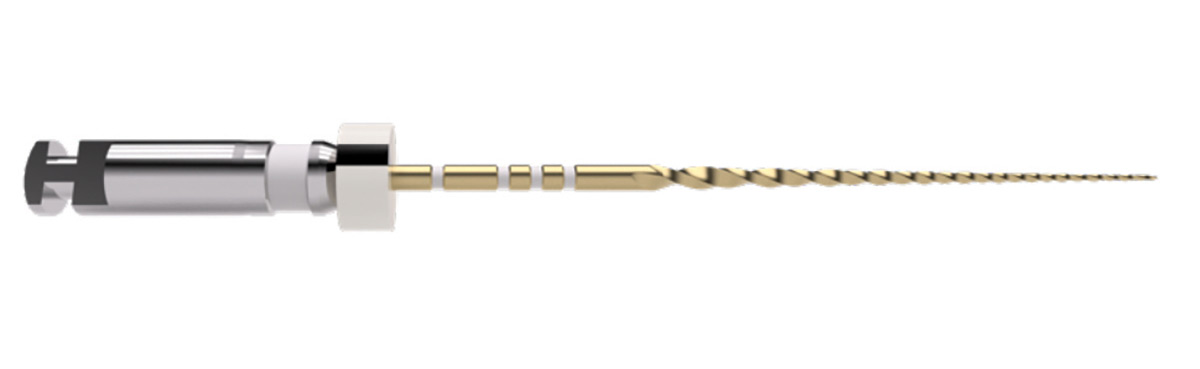
Fig. 4

Fig. 5
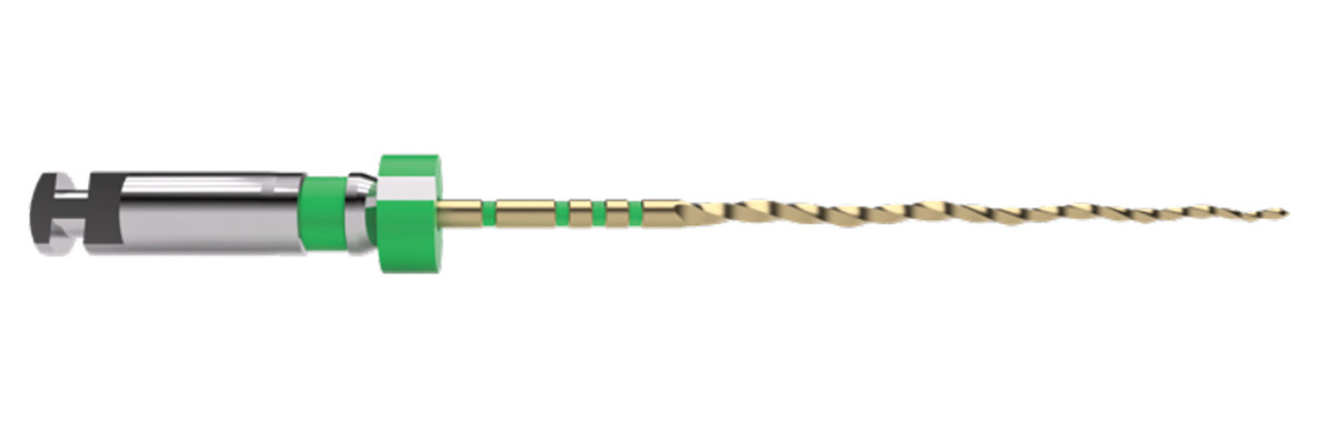
Fig. 6

Case Report 1
The patient, a 25 year old female, presented with irreversible pulpitis on her maxillary left first premolar that had a history of a previous pulp cap procedure and a large class II composite restoration. Figure 7A shows the pre-operative periapical radiograph and orifice modification with the TruNatomy Orifice Modifier).
After glide path preparation with stainless steel K-Files and the TruNatomy Glider (Figure 7B), both root canal systems were prepared with a single TruNatomy Prime instrument (Figure 7C). Two TruNatomy Prime Conform Fit GuttaPercha cones were placed and the fit confirmed radiograpically (Figure 7D). Figure 7E shows the post-operative result after root canal obturation using the continuous wave of condensation technique (Calamus Dual Obturation Unit, Dentsply Sirona) with AH Plus Root Canal Sealer (Dentsply Sirona) and two TruNatomy Prime Conform Fit Gutta-Percha Points.
Fig. 7A

Fig. 7B
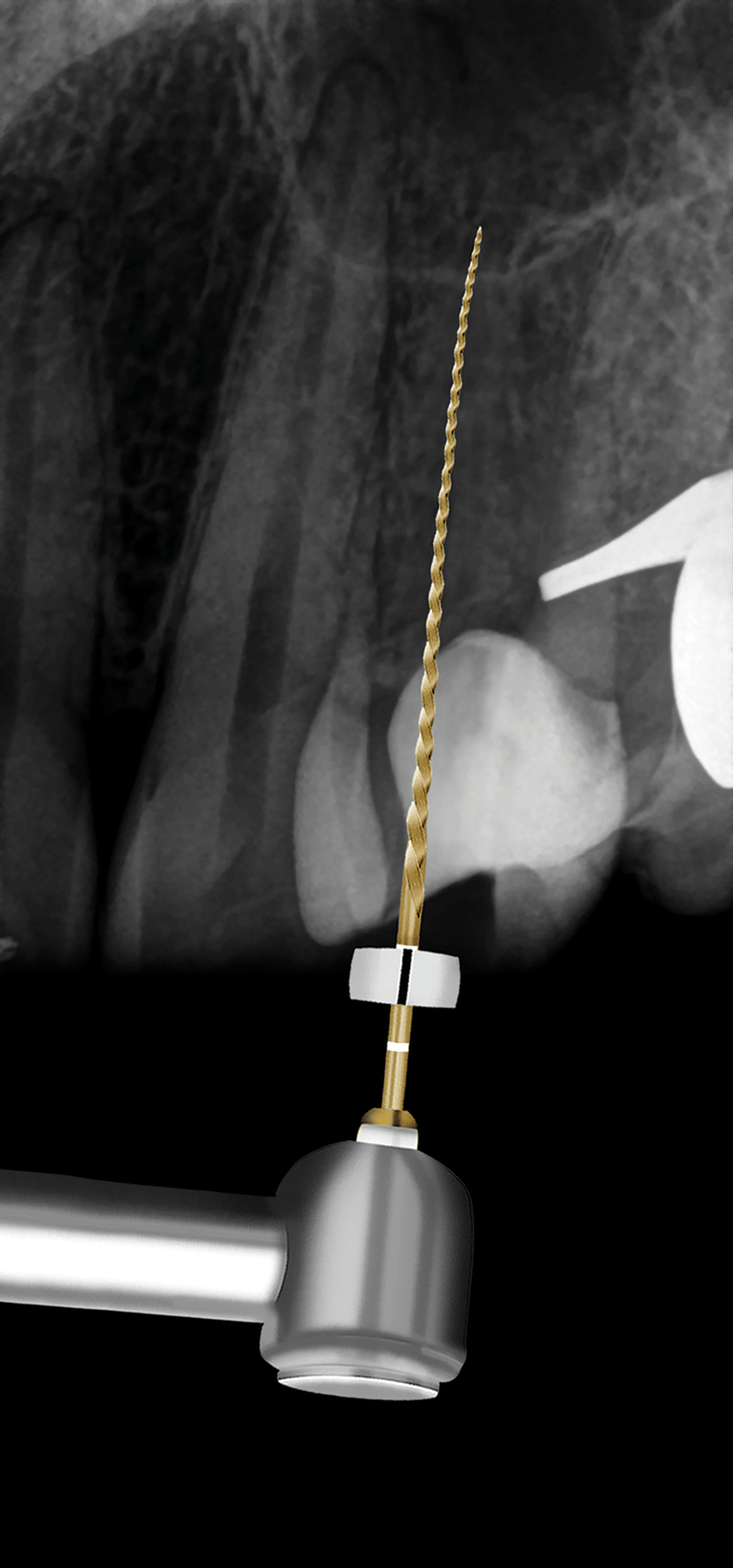
Fig. 7C

Fig. 7D

Fig. 7E

Case Report 2
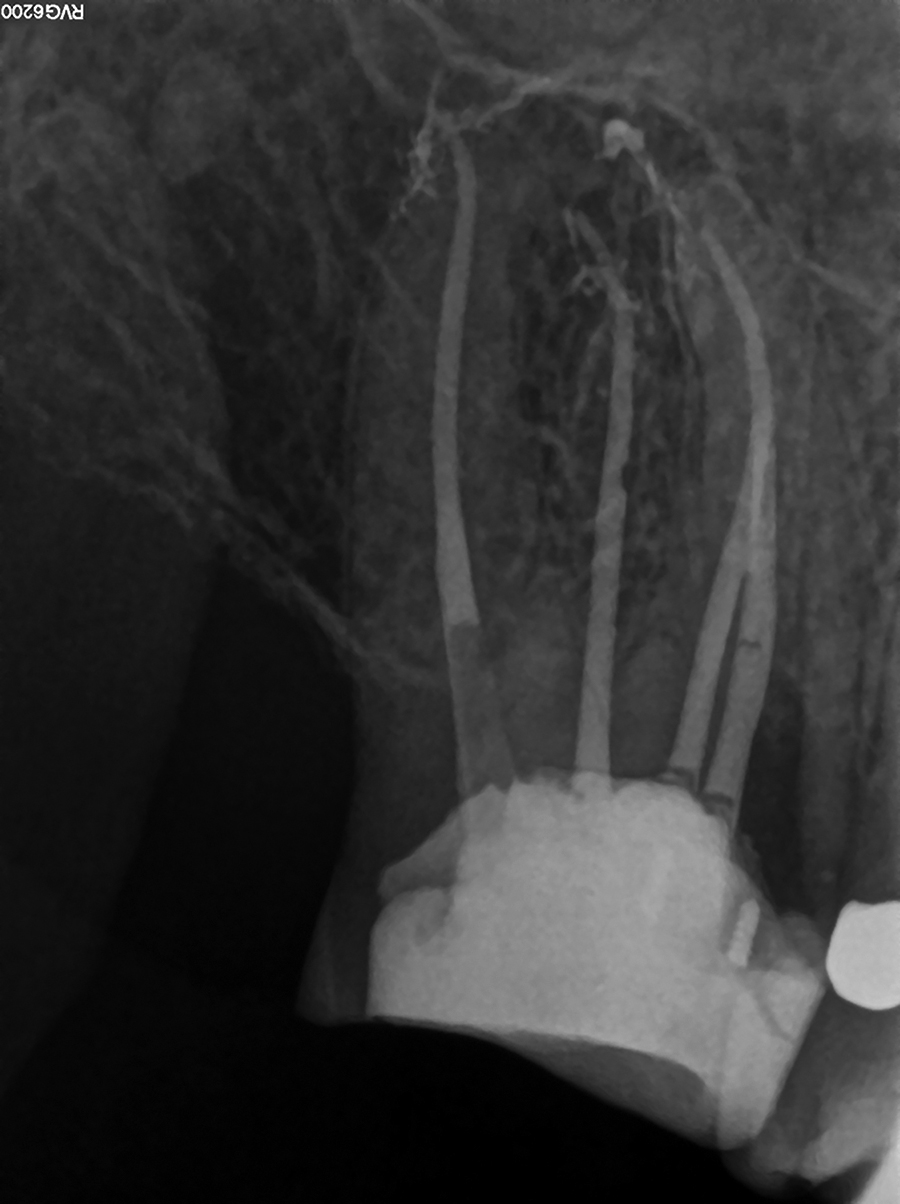
The patient, a 58 year old male presented with a non-vital maxillary right second molar. A pre-operative periapical radiograph revealed a very deep, previously placed composite restoration (Figure 8A). After access cavity preparation four root canal systems were detected (two mesiobuccal, distobuccal and palatal). After orifice modification with the TruNatomy Orifice Modifier and glide path preparation with K-Files and the TruNatomy Glider, the four root canals systems were prepared with a single TruNatomy Prime instrument. The fit of four Prime TruNatomy Conform Fit Gutta-Percha Cones were confirmed radiographically before the root canal systems were obturated (Figure 8B). Figure 8C depicts the post-operative result after obturation of the root canal systems and placement of fiber post and composite core. The clinical procedure of this case can be viewed on the following link: https://youtu.be/OplAENoh3b8
Fig. 8A
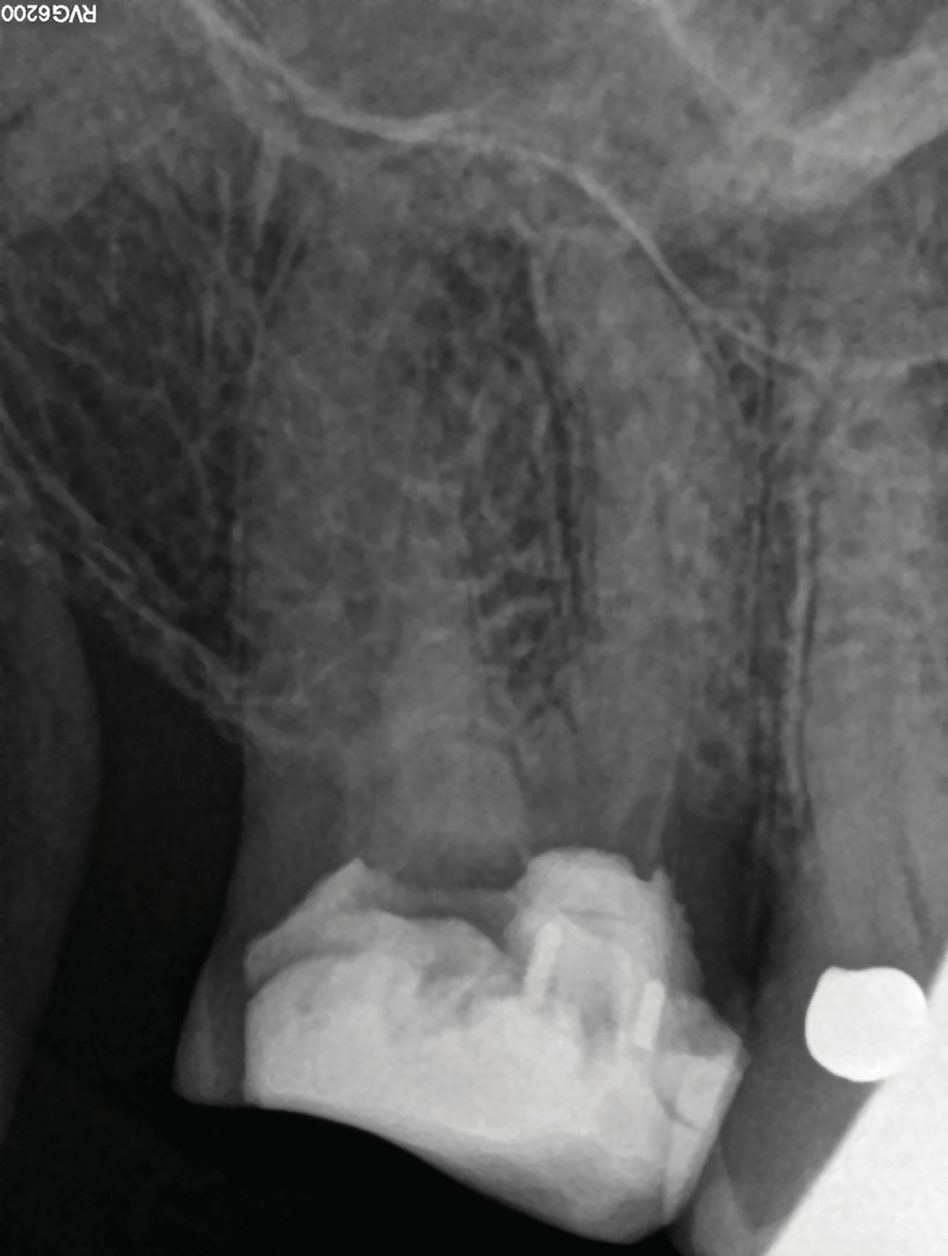
Fig. 8B
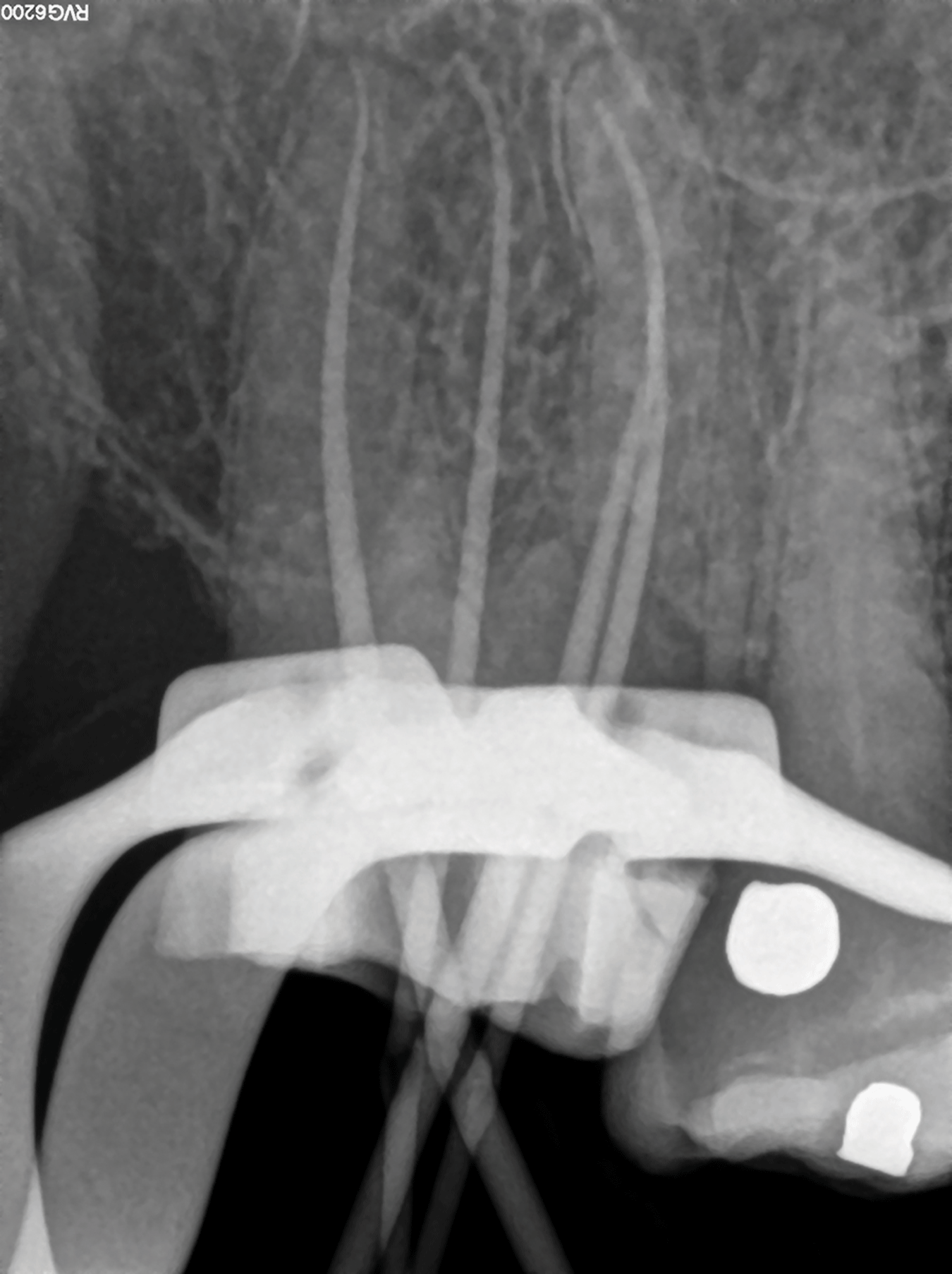
Fig. 8C
Case Report 3
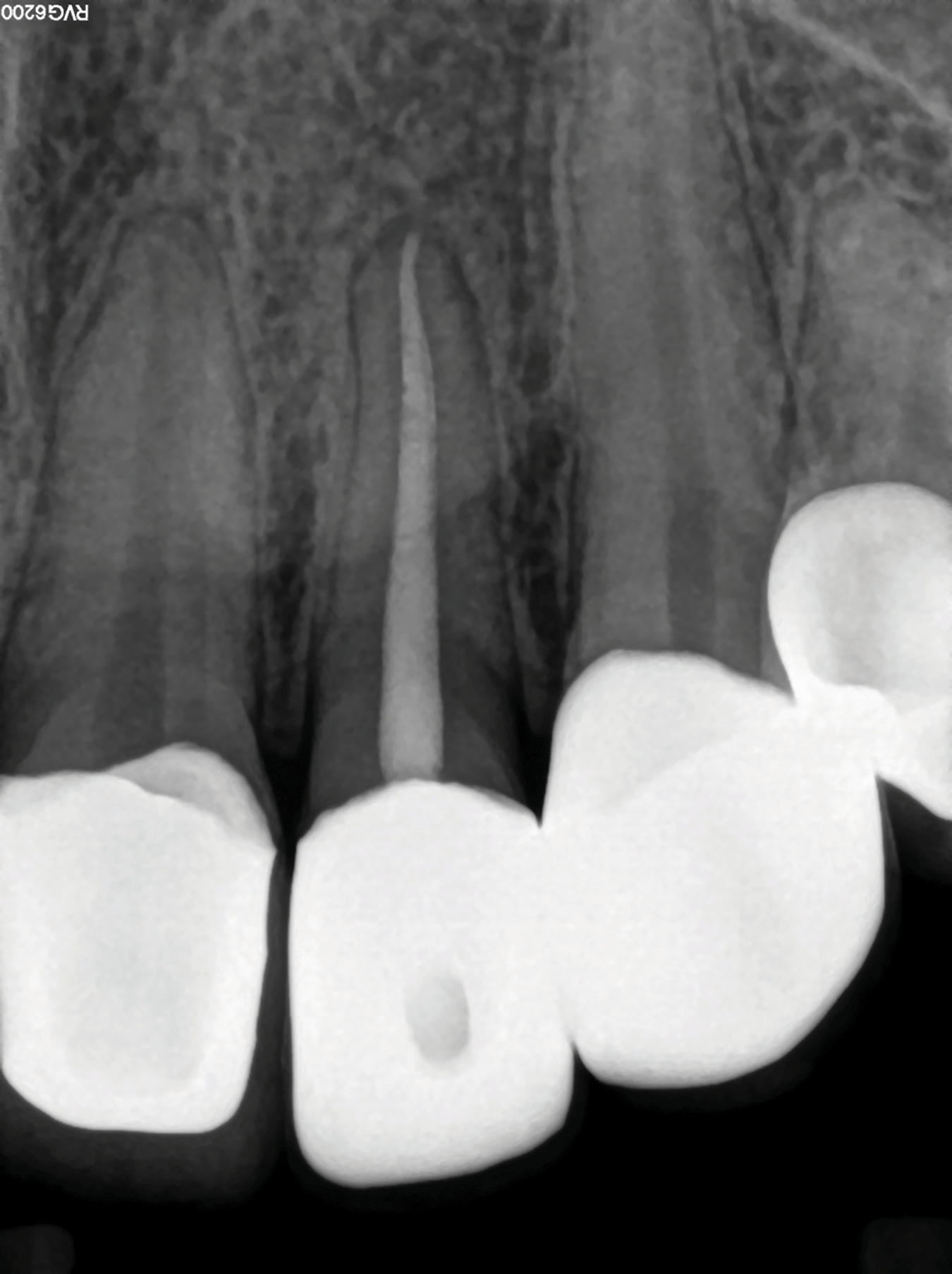
The patient, a 30 year old female presented with a non-vital maxillary left lateral incisor previously restored with a zirconia crown (Figure 9A). After access cavity preparation, the canal was located and a size 20 K-File was used for length determination (Figure 9B) using and electronic apex locator. The size 20 K-File was loose in the canal it was decided to complete canal preparation with a single TruNatomy Medium instrument. A size Medium TruNatomy Conform Fit Gutta-Percha Cone was placed and the fit confirmed radiographically (Figure 9C). Figure 9D illustrates the post-operative radiograph after the canal was obturated using the continuous wave of condensation technique (Calamus Dual Obturation Unit) with Pulp Canal Sealer (Kerr) and a Medium TruNatomy Conform Fit Gutta-Percha Point. The clinical procedure of this case can be viewed on the following link: https://youtu.be/sG5paE_2FN4
Fig. 9A

Fig. 9B

Fig. 9C

Fig. 9D
Case Report 4
The patient, a 65 year old male, presented with a non-vital maxillary right second premolar with a history of a previous emergency root canal treatment and placement of calcium hydroxide as an intracanal medicament. The temporary restoration and calcium hydroxide paste was removed before length determination was done using an electronic apex locator and the working length confirmed radiographically. The canals were extremely difficult to negotiate and when the size 08 K-Files that was used for length determination were removed, it was noted that the buccal root canal system presented with an S-curvature.
A size 08 and 10 K-File was used to secure a reproducible micro glide path before the glide path was expanded using the TruNatomy Glider. It took several passes with the glider before working length was reached in both root canals. Taking into account the fact that glide path preparation was extremely difficult and the fact that the buccal root canal presents with an S-curve (not visible on periapical radiographs), it was decided to complete canal preparation with the TruNatomy Small instrument. After canal preparation, two TruNatomy Conform Fit Small Gutta-Percha cones were placed and the fit confirmed radiographically. Again, upon removal of the cone from the buccal root canal, the S-curvature was imprinted on the gutta percha cone. This confirmed that the TruNatomy file maintained the original root canal anatomy. The canals were obturated using the continuous wave of condensation technique (Calamus Dual Obturation Unit) with Pulp Canal Sealer and two Small TruNatomy Conform Fit Gutta-Percha Points. The clinical procedure of this case can be viewed on the following link: https://youtu.be/FaK0tXqULM8
Fig. 10A

Fig. 10B

Fig. 10C
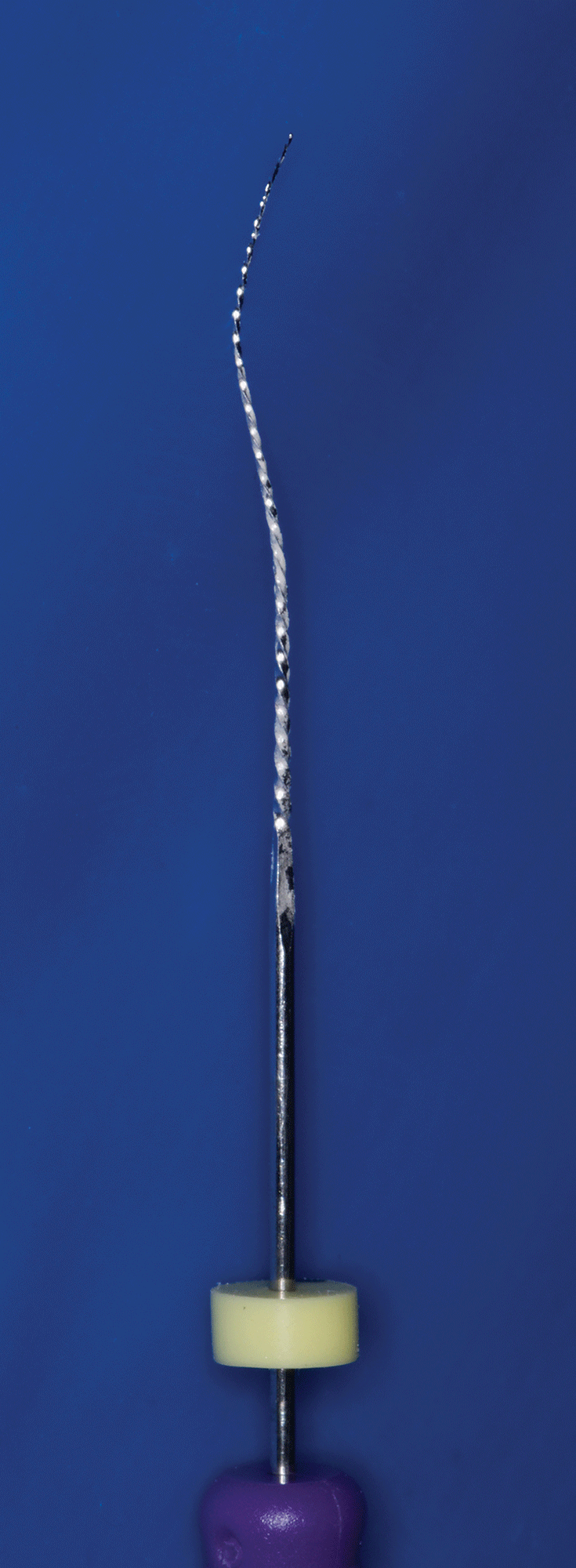
Fig. 10D

Fig. 10E

Fig. 10F

Case Report 5
The patient, a 71 year old male presented with irreversible pulpitis on his mandibular maxillary right first molar previously restored with a zirconia crown (Figure 11A). An access cavity was prepared and four root canal systems were located followed by length determination using and electronic apex locator. After orifice relocation using the TruNatomy Orifice Modifier a glide path was prepared using stainless steel K-Files and a TruNatomy Glider. Root canal preparation was done with a single TruNatomy Prime instrument. Figure 11B illustrates postoperative radiograph after the canal was obturated using the continuous wave of condensation technique (Calamus Dual Obturation Unit) with Pulp Canal Sealer and four Prime TruNatomy Conform Fit Gutta-Percha Points. Note the conservative coronal root canal preparations in the peri-cervical area. Figure 11C depicts a mesio-angulated view showing the four obturated root canal systems.
Fig. 11A
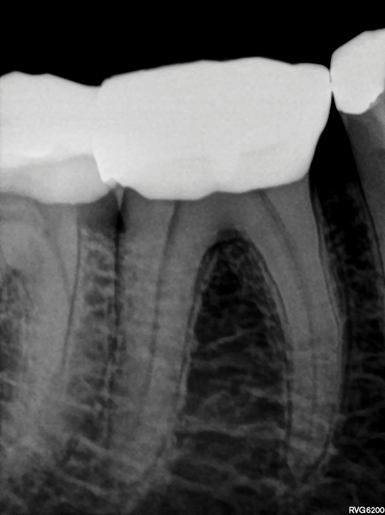
Fig. 11B
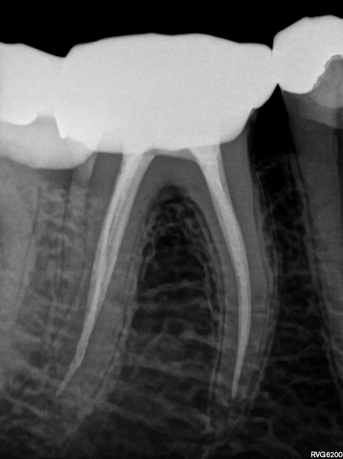
Fig. 11C
Case Report 6
A 45 year old female presented with irreversible pulpitis on her mandibular right first molar (Figure 12A). A pre-operative CBCT scan revealed the presence of a mid-mesial root canal system in the mesial root (Figure 12B). After access cavity preparation, and removal of pulp calcifications in the pulp chamber, the three main root canal systems were located (mesio-lingual, mesio-buccal and distal). The groove between the mesio-lingual and mesio-buccal canals was throughed with a Start-X no 3 tip (Dentsply Sirona) to remove an overlapping dentine ledge, exposing the internal anatomy of the groove. A Micro-debrider (Dentsply Sirona) was used to locate the orifice of the mid-mesial canal. A size 08 C+ File (Dentsply Sirona) was used to negotiate the initial few millimetres of the constricted canal.
Fig 12A

Fig. 12B

Canal orifices were relocated and opened coronally with the TruNatomy Orifice Modifier before the three mesial root canal systems were negotiated to full working length and apical patency. It was noted clinically and on CBCT that the distal root canal system was very wide in a buccal-lingual direction (Figure 12B) and it was possible to place a size 20 KFile to full working length.
Working lengths were determined by using an electronic apex locator and confirmed radiographically (Figure 12C and 12D). It was noted that the mid-mesial canal join the mesio-lingual canal and the mesio-lingual join withn the mesiobuccal canal in the apical 2mm of the root canal system. A reproducible micro glide path was established in all five root canal systems using a size 08 and 10 KFile before the glide paths were expanded with the TruNatomy Glider.
Fig. 12C
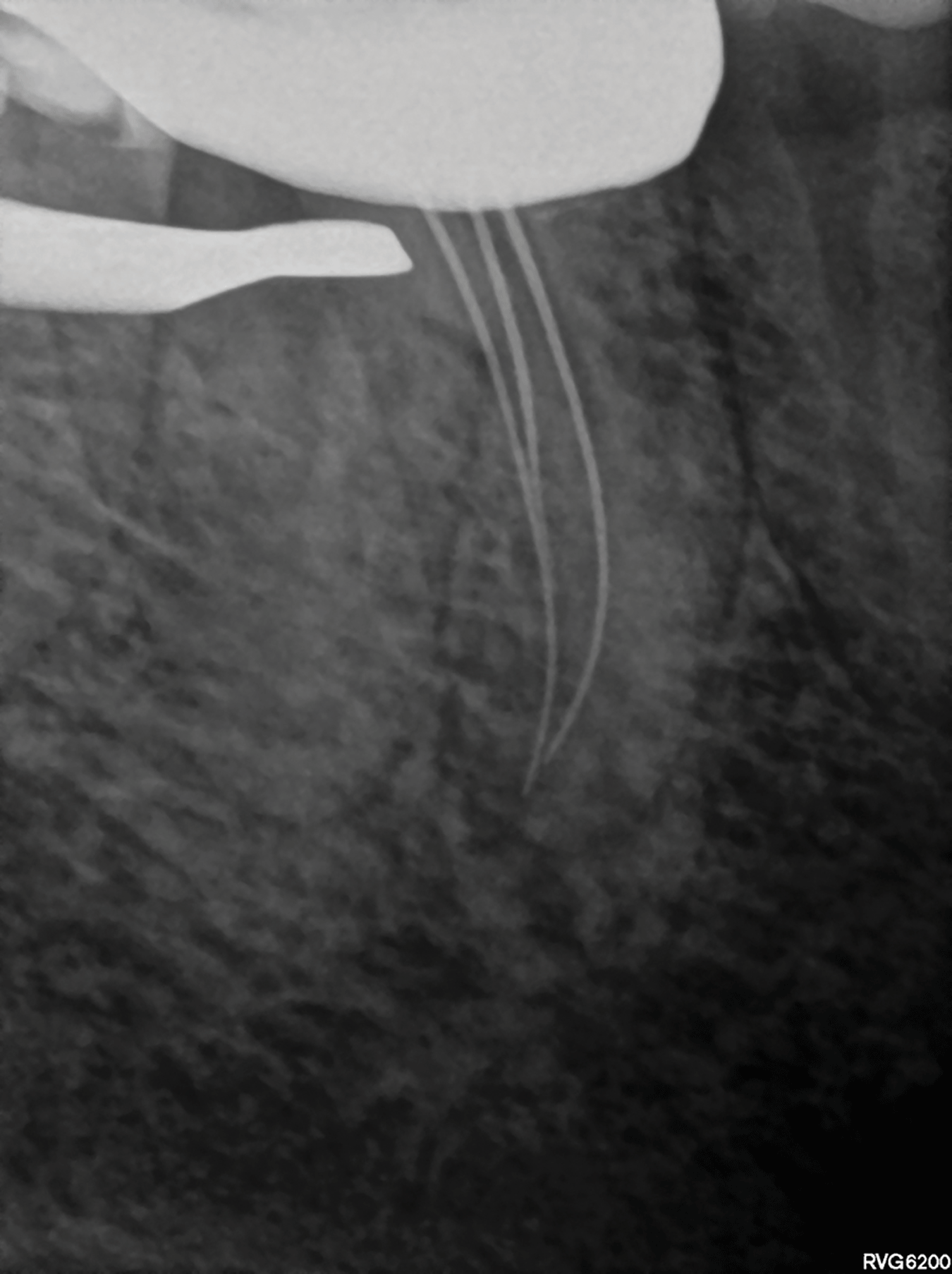
Fig. 12D

Taking into account that there was three root canal systems in the mesial root, the authors decided to use the TruNatomy Small file for root canal preparation and maximum preservation of root structure. Figure 12E shows a magnified view of the pulp chamber floor. Note the large amount of tooth structure that was still intact after root canal preparation with the TruNatomy Small file. The distal root canal was prepared with a TruNatomy Medium file.
Fig. 12E

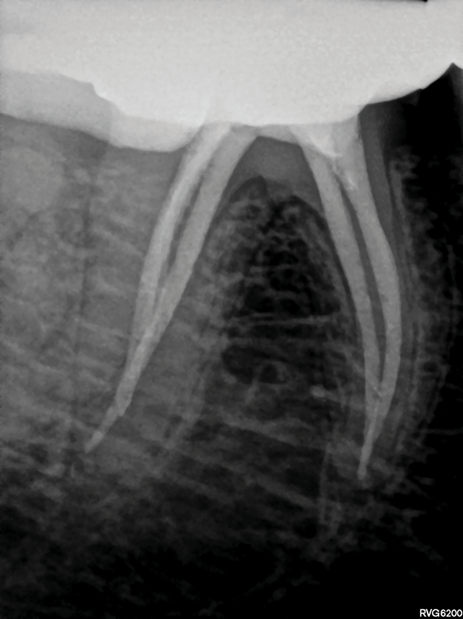
Root canal irrigation was achieved by using 17% EDTA and heated 3.5 % sodium hypochlorite activated with the EDDY Endo Irrigation Tip (VDW) driven by an airscaler. Obturation of the canals were achieved by using TruNatomy Conform Fit Gutta-Percha cones and TotalFill BC Sealer Highflow (FKG) using the continuous condensation technique. Figure 12F shows a parallel view of the obturation result. Note the maximum preservation of the root structure in the peri-cervical region of the mesial and distal root canal systems. However, the mesio-angulated view (Figure 12G) shows that the full extend of the lateral anatomy that was cleaned and obturated. The clinical procedure of this case can be viewed on the following link: https://youtu.be/MxVKMcE2VM
Fig. 12F
Fig. 12G

Conclusion
Respecting original canal anatomy, preserving dentine and therefore maintaining the structural integrity of teeth should form an integral part of root canal shaping and preparation. In this paper the authors illustrate the clinical guidelines, applications and advantages of the recently launched TruNatomy system. With a renewed focus on dentine preservation and benefits like improved performance and efficacy the TruNatomy instruments offer the clinician superior debridement whilst respecting original canal anatomy.
Corresponding Author: PJ van der Vyver Studio4Endo.com, e: peetv@iafrica.com © Copyright Prohibited
Disclaimer: Reprinted with permission by International Dentistry – African Edition Van der Vyver PJ, Vorster M, Peters OA. Minimally invasive endodontics using a new single-file rotary system. Int Dent – Afr Ed. 2019;9(4):6–20.
References
- Bürklein, S., Hinschitza, K., Dammaschke, T., Schäfer, E. (2012) Shaping ability and cleaning effectiveness of two single file systems in severely curved root canals of extracted teeth: Reciproc and WaveOne® versus Mtwo and ProTaper. Int Endod J 45: 449-461.
- Clark, D. & Khademi, J. (2010). Modern molar endodontic access and directed dentin conservation. Dent Clinics 54: 249-273.
- Gluskin. A.H., Peters, C. I. & Peters, O. A. (2014) Minimally invasive endodontics: challenging prevailing paradigms. Br Dent J 216:347-353.
- Herbranson E. (2014) Microendodontics? Roots, North America Edition 8(3).
- Papa, J., Cain, C. & Messer, H. (1994) Moisture content of vital vs endodontically treated teeth. Dent Traumatol 10: 91-93.
- Ng, Y.L., Mann, V., & Gulabivala, K. (2010) Tooth survival following non-surgical root canal treatment: a systematic review of the literature. Int Endod J 43: 171-189.
- Sedgley, C. M. & Messer, H. H. (1992) Are endodontically treated teeth more brittle? J of Endod 18: 332-335.
- Tang, W., Wu, Y. & Smales, R. J. (2010) Identifying and reducing risks for potential fractures in endodontically treated teeth. J of Endod 36: 609-617. 9. Van Der Vyver P (2011) WaveOne® Instruments: Clinical application guidelines. Endod Prac 11: 45-54.
About the Authors
 Prof Peet J van der Vyver, Studio for Endodontics, Restorative Dentistry and Dental Education (www.studio4endo.com); Part-time lecturer at the University of Pretoria, Department of Odontology, School of Dentistry, University of Pretoria, Pretoria, South Africa.
 Dr Martin Vorster, Lecturer/Dentist at the University of Pretoria’s School of Dentistry, Pretoria, Gauteng, South Africa. (martin.vorster@up.ac.za) Department of Odontology, School of Dentistry, University of Pretoria, Pretoria, South Africa.
 Prof Ove A Peters, Professor and Chair, Department of Endodontics, University of the Pacific Arthur A. Dugoni School of Dentistry, San Francisco, CA, USA and University of Queensland Oral Heath Centre, Herston Qld, Australia.
Please click here to view the entire May 2020 Endodontics issue!


