
Introduction: Masterful Final Impressions
The excellence and marginal fit of definitive laboratory restorations can only be as good as the master dies and impressions from which they are created. The precision of the master impression cannot be compromised. Marginal detail and tooth structure apical to the restorative margin are both necessary elements of an acceptable final impression. It is essential for the dentist to critically reject all but the “perfect” master impression. The traditional uses an elastomeric material that is injected around the preparations and loaded into an impression tray, then placed in the oral cavity where it then sets up to a rigid consistency. The set impression is removed from the oral cavity minutes later, disinfected, and sent to the laboratory with an opposing arch impression and interocclusal records. The laboratory thus has a “duplicate” of the patient on which to fabricate the prescribed restoration.
CAD/CAM dentistry and “digital work flow” have developed technologies whereby preparations are scanned by a device similar to an intraoral camera, and sent to the laboratory via email, giving a milling machine all the necessary digital information to create precise master models, dies, and completed restorations without any conventional impression materials. Clinically, this is advantageous; the master models are more accurate, and scanned impressions can be easier on the patient than conventional ones (gagging patients, mandibular tori, etc.) Some patients also just don’t do well with a “mouth full of goop” that takes several minutes to set. A discussion of digital scanning and traditional impression making techniques follows:
Restorative Margin Placement Is Dictated by the Restorative Material Chosen
Current aesthetic materials allow the restorative margin to be located supracrevicular (above the gingival tissues), equicrevicular (at the free gingival margin), or intracrevicular (in the gingival sulcus). Porcelain fused to metal crowns are typically more esthetic with intracrevicular margin placement. All ceramic restorations can often be placed at the free gingival margin, or in the case of “contact lens” porcelain veneers, slightly supragingival, which is the ideal location for dentin and enamel bonding procedures. It is important to remember that a scanned “digital impression” cannot “see” through the gingival tissues or through fluid (hemorrhage or crevicular fluid) in the sulcus. The optical scanner must clearly “see” the restorative margin as well as the tooth or root surface just apical to the margin to create an accurate master die. Digital impression accuracy therefore requires appropriate tissue management and retraction technique!
Tissue Management for Optical Scanning Is the Same as For Conventional Impressions
The digital scanning workflow makes it convenient to scan the opposing arch while the anesthetic is setting in. Depending upon the number of teeth, or types of restorations that are planned, a quadrant scan, or full arch scan is indicated. Once the preliminary preparation data is entered into the patient’s record, the software instructs the operator which views are required. After completing equicrevicular or intracrevicular tooth preparation, the soft tissues surrounding the preparation must be retracted, or deflected away from the margin, such that there is no fluid contamination in the sulcus prior to the scanning process. There are several ways to accomplish this task.
1) Two Cord Tissue Retraction
A two-cord impression technique is utilized for master impressions for full coverage (circumcoronal) and facial veneer restorations (both intracrevicular and equicrevicular margins). First, a #00 cord (UltraPak: Ultradent) is packed around each preparation margin starting from the lingual proximal to the facial, then back through the remaining proximal area to the lingual. The excess cord at both lingual ends is trimmed, and the ends of the cord are tucked into the lingual gingival sulcus such that their ends abut. If desired, the cords may be soaked in a hemostatic solution and then dried with a 2X2 gauze prior to placement. Next, a #1 cord (UltraPak: Ultradent) is placed on top of the #00 in the same fashion as previously described. The preparation is cleansed with dentin desensitizer on a cotton pledget. Then, the #1 cord is teased out of the sulcus using an explorer tine from the facial aspect of each preparation; the amount of retraction is evaluated. The optical impression should capture not only the entire restorative margin, but also about .5 millimeters of the tooth/root surface apical to the margin. If the marginal gingiva adjacent to any restorative margin rebounds to contact the tooth/margin, a small segment of a larger diameter cord (#2) is placed into the affected area for an additional minute, and then removed prior to scanning. This added retraction should be sufficient to create a space between the tooth surface and the inner lining of the gingival sulcus. The goal of retraction is to create a moat (space wherein the optical scanner clearly “sees” the margin and tooth surface) around the castle (tooth preparation).
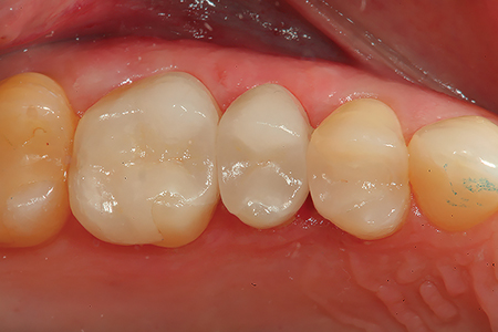
2) Troughing the Gingival Sulcus with a Dental Laser
Troughing creates a space between the preparation margin and the soft tissues with a diode laser. In many cases, troughing alone will allow adequate visualization of the restorative margin and emergence profile for an accurate scan. Additionally, lasers are helpful in hemostasis, very easily and quickly creating the ideal scanning environment. Troughing is recommended only when there is enough horizontal thickness and attached gingiva (keratinized tissue) present such that it does not result in the loss of vertical tissue height or invasion of the muco-gingival junction. Be wary of thin periotypes and low crest bone positions relating to biologic width as they are prone to gingival recession. Overall, a diode laser is much more predictable than using electrosurgery where gingival troughing is indicated. Electrosurgery instruments generate an unpredictable zone of necrosis (particularly in thin sulcular environments) and can cause excessive recession and gingival sloughing. Since laser troughing necrosis is reportedly much less, excessive collateral damage is less likely. It is still a good practice to use mechanical (cord) tissue retraction, particularly in the esthetic zone (facial aspect). Gingival troughing is indicated for localized gingival excess, chronic inflammation, and areas outside the esthetic zone. The ultimate goal is to capture the margins and 0.5mm of root surface apical to the margin. This allows the laboratory to create an appropriate emergence profile. In some cases, retraction cord can be also be used to displace tissue tags that may be left from laser troughing. (Figs. 1-6)
Fig. 1
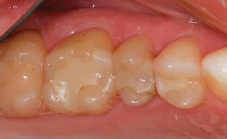
Fig. 2
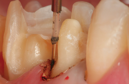
Fig. 3
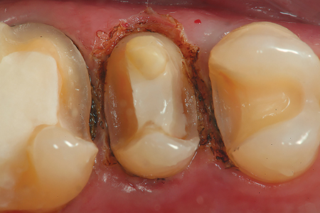
Fig. 4

Fig. 5
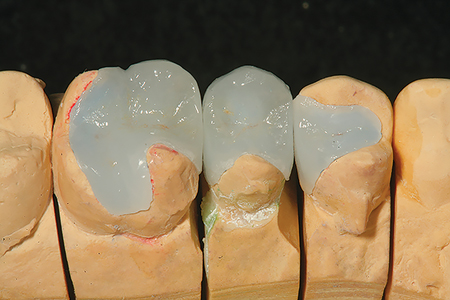
Fig. 6
Digital Scanning of the Prepared Tooth
Digital scanners can quickly scan half arch and full arch cases by video streaming. Most enables the practitioner to view the scan in real time to ensure that all critical areas are covered and the segments can be “stitched” together. The digital software allows the dentist to review, in three dimensions, the case upon scan completion prior to sending the information to the lab. In fact, the software indicates critical area occlusal clearance of the prepared tooth. Should there be inadequate space for an optimal restoration, the dentist can make immediate corrections, rescan, and the software will correct the virtual model. This eliminates the need for reduction copings and/or additional patient visits. The entire scanning process (average case) takes about 2 minutes from start to finish. (Figs. 7-16).
Fig. 7
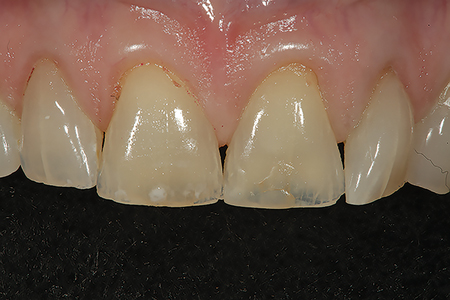
Fig. 8
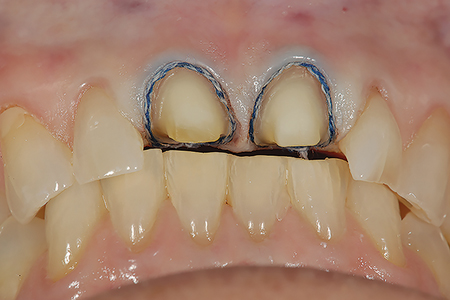
Fig. 9

Fig. 10

Fig. 11
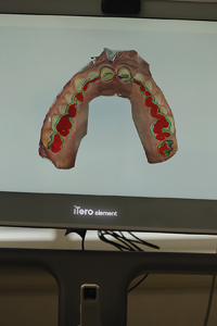
Fig. 12

Fig. 13
Fig. 14
Fig. 15
Fig. 16
A Comparison of Digital Scanning and Conventional Impression Making
The rapid advent of impression scanning technology has not resulted in an equally rapid decline of conventional impression materials. The main “roadblocks”, common to all new technologies, are cost and “return on investment”. The typical full arch conventional impression (heavy body tray material and injectable light body) costs approximately $10. Most associated procedural costs (model work, pouring, duplicate dies, etc.) are included in the laboratory “per unit fee”. Digital scanners can cost $20,000 or more, and often generate additional “processing fees”, that are passed along to the dentist and the laboratory for the “convenience” of creating each digital model. The advantages of digital models include that they are not made of dental stone. Digital models are milled to consistent accuracy; there is no possibility of inaccuracy due to improper powder/water mix ratios (dental stone), chipping, or abrasion of the dies, etc. The digital image can be manipulated in “3D” to preview all aspects of the prepared arch, the opposing arch, and the model in occlusion. If further reduction for restorative material clearance is needed, the preparation can be corrected immediately, and the scan updated. Many “scanning” clinicians promote the digital technique as “less invasive for the patient” (no “mouth full of goop” during the impression, or gagging). Each dentist must determine individually whether the benefits offset the cost. A well-made conventional impression including all preparation margins and emergence profiles can yield a quality definitive restoration in the hands of an excellent dental technician.
Last but not least, there can be no comparison between the artistic ability of a skilled ceramist and the programming of milling machines to create the high levels of anatomic and occlusal detail. In many cases, occlusal anatomic detail and ideal occlusion are “sacrificed” for the speed and lower cost of monolithic milled restoratives. Again, the choice is up to the individual dentist, but these are points to consider; some practitioners prefer milled substructures with custom anatomic characterization placed with powder and liquid by the ceramist. Another option on the horizon is a tabletop, in-office device that scans a conventional impression and converts it to digital data which then can be transmitted online to the laboratory digital workflow. This may prove to be a less expensive means for integrating digital workflow with conventional impression methods. Only time will tell…..
Oral Health welcomes this original article.
About the Author
 Dr. Robert A. Lowe graduated magna cum laude from Loyola University School of Dentistry in 1982. He maintains a private practice in Charlotte, North Carolina, publishes and lectures internationally on aesthetic and restorative dentistry. Dr. Lowe can be reached at 704-450-3321 or at boblowedds@aol.com


