
Introduction
Complete maxillary implant rehabilitation presents great challenges in achieving optimal aesthetic outcomes. The aesthetic component of the rehabilitation can often be unpredictable and not satisfy patients’ expectations, which implies the need of highly well done pre-operative examination and treatment planning. In patients with a high lip line, the transition between the implant prosthesis and the adjacent soft tissue, known as the transition line, is a critical factor in the final aesthetics of the restoration.1 The goal of this case presentation is to provide a protocol that will help to predictably determine the transition line of the final prosthesis. Correctly predicting and managing this transition line is of paramount importance and will often determine the ideal type of restoration when planning a case where aesthetics are a priority. This can make the difference when planning for a fixed or removable prosthesis. It will also provide the patient with a realistic expectation of the size and position of the anterior teeth. 3D technology that includes a CBCT scan, computer parametric software2 and optical scanning can be used to diagnose, treatment plan and provide guidance for every phase of patient care. In this paper, we take advantage of these advances in supportive technology to predict the transition line of an immediate complete maxillary implant prosthesis.
Materials and Method
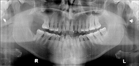
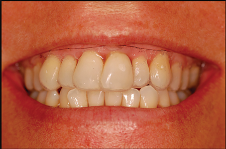
A 53-year-old female patient required rehabilitation of her maxillary dentition. Her chief complaint focused on the appearance of her teeth. She was concerned about the alignment as well as the length of her teeth due to gingival recession. The clinical evaluation revealed generalized severe chronic periodontitis (Fig. 1). Several teeth had significant mobility, deep periodontal pockets and furcation involvement. A hopeless prognosis was assessed for her maxillary dentition and some alternative treatment plans were presented for both arches of the patient.
Figure 1
Pre-op 2D panoramic displays generalized horizontal bone loss and localized vertical bone loss. Multiple tooth mobility were at the maxillary, for a total of eight teeth (no. 14, 15, 12, 21, 22, 16, 26 and 27). Multiple furcation exposure, inter dental spaces and food retention were also observed.
The approved treatment plan was to remove all of the patient’s remaining maxillary teeth and provide her with a complete maxillary implant supported restoration. For financial reasons, the patient elected to have only her upper arch treated at this time with the intention of treating her lower arch at a later time. In this paper, we will present in detail the steps used to determine the transition line of her immediate complete maxillary implant prosthesis.
Complete records were taken which included study models, photos, and a CBCT scan. The study models were optically scanned so as to digitalize them. The digital models, photos and CBCT were all integrated, by using the advanced planning software (Simplant, Materialise Dental, Dentsply, Belgium) to predictably plan both the surgical and restorative phases of her restoration.
Innovation
The transition line is by definition the junction of the prosthesis with the soft tissue over the residual ridge and thereby predicting the transition line is critically important in planning for the final prosthesis. With this in mind, teeth were virtually extracted by means of the implant planning software (Simplant). This allowed the virtual visualization of the remaining supporting bone architecture (Fig. 2). A measurement was taken from the tip of the maxillary incisors on the optical scan of the patient study model to the bone crest on the CBCT scan (Carestream, CS9300 Select, Kodak, USA) that had previous teeth extracted virtually (Fig. 3). That measurement was then replicated on the patient’s maxillary study model.
Figure 2
CBCT scan of patient’s maxilla with virtual teeth extraction. One can observe the bone resorption morphology from periodontitis condition.

Figure 3
A superposition of an optical scan of the maxilla diagnostic cast is overlaid on aCBCT. Measurements from the incisal teeth tip to the bone crest are draw and recorded on the study cast. These measurements determine the bone crest topography in the aesthetic zone.

On the previous measurements of the scan superposition, a white line is drawn to connect the dots. A line representing the bone crest on the study model was then visualised (Fig. 4). Another line (red) is drawn 2 mm incisal to the bone crest line. Predictably, within the months following the extractions, the bone crest will be covered with soft tissue of approximately 2 mm in thickness.3 A vacushell was then adapted on the stone cast and trimmed at the predicted soft tissue line (red line). The vacushell border determined the transition between the implant prosthesis and the pre-maxilla soft tissue; the predicted transitional line. This vacushell was fitted on the patient’s upper arch to evaluate the predicted soft tissue transition line. The patient is asked to speak and smile with the vacushell in place. Hence, the vacushell is tested during static and dynamic lip movement (Fig. 5). The goal of this innovation is to be able to foresee and locate the transition line within dynamic lip movement prior to surgery, and to predict the final prosthetic outcome.
Figure 4
On the previous measurements of the scan superposition, a white line is draw to connect the dotes. Another line (red) is draw 2 mm incisor to the bone crest line. That 2 mm space between the lines reproduces the thickness of the soft tissue after teeth extraction. A vacushell was prepared and trim to this red line.
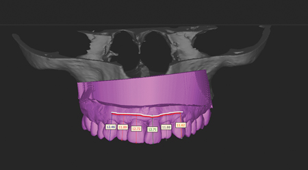
Figure 5
A vacushell was made on the study cast and trimmed to the CBCT data. The vacushell upper limitation represents thepredicted soft tissue profile (transitional line). The patient was ask to smile and talk with this vacucshell to visualize thepredicted soft tissue transitional line. Soft tissue is exposed beyond the vacushell gingival aspect, this depicts a predictable gummy smile result after surgery.
This clinical case study presented a transition line that was partially exposed in the aesthetic zone during the patient’s lip movements. In her case, different options are available to avoid the exposure of this transition line in the patient’s smile:
1. Prepare a removable prosthesis with a vestibular extension that will end under the patient’s maxillary lip.4
2. Use a paralysing effect created by Botox injections of the upper lip to reduce the mobility of that lip and avoid the exposure of this transition line.5
3. Surgically relocate the maxillary lip in a lower position, again to reduce the exposure of the transition line.6,7
4. Osteoplasty to reduce the crestal bone allowing implant placement more apically and thus move the transition line under the lip.
The patient elected the forth option.
Planning For Immediately Loaded Implants In The Aesthetic Zone
Based upon the literature, we propose here eight diagnostic keys for the risk assessment when planning for immediate implants in the aesthetic zone. The first five diagnostic keys are from Kois publication.8
Key no. 1, Tooth Position8
If the natural tooth is in a coronal or lingual position in relation to the soft and hard tissues, this will generally present as a thick biotype. This places less risk of a dehiscence at the time of implant placement. In situations where the natural tooth is situated in a buccal or apical position the soft tissue will generally present as a thin biotype. In these situations there is a greater risk of dehiscence around the implant.
A hopeless tooth with the free gingival margin positioned ideally or more apically then it’s adjacent teeth, would benefit from orthodontic extrusion before extraction. In this way, the apical resorption after wound healing can provide a more harmonious gingival level.
Key no. 2, Gingival Form
A high gingival scallop on the natural tooth will increase the risk of implant dehiscence. In this architecture, there is more tissue coronal to the bone interproximally than facially for this scallop. The greater this discrepancy, the higher the scallop and the higher the risk for gingival loss after
extraction.
The higher the soft tissue on the buccal of an incisor, the less predictable the final outcome of the peri-implant soft tissue. A flat gingival scallop will be more predictable because of the larger availability of the tissue around the natural tooth on the implant replacement. A flatter gingival scallop tends to mimic the osseous scallop, creating less discrepancy and more predictable maintenance of the interproximal papilla.
Key no. 3, Biotype
A thick biotype is considered when the gingival thickness is over 1 mm. Clinically if a periodontal probe is not visible through the gingival tissue when placed into the sulcus, the biotype is then considered thick. Thicker tissue is usually more resistant to recession. A thick biotype will be favourable for an immediate implant procedure. The thin gingival biotypes are often friable and result in increased risk of facial recession and interproximal loss of gingival tissue after any surgical procedure.
The thickness evaluation is more subjective in nature. Several conditions can affect this clinical observation such as; pigmentation of the soft tissue, probe color, a yellow colored probe will be more visible and will influence the operator judgment.
With the CBCT and optical scans superimposed, one can potentially visualise the soft tissue to bone and have a submillimeter measure of the biotype thickness. Therefore, a metric replaces a subjective measure and becomes more predictable in this key evaluation.
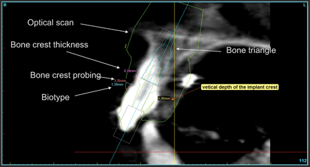
An optical scan of the study cast is superimposed on a CBCT scan (Fig. 6). One must note that an optical scan will give a 40-micron precision for the impression. Therefore, all measurement will have a 40-micron precision. On this orthogonal cut, digital metrics replace manual and subjective measurements; biotype thickness, bone crest probing depth, bone crest thickness. Root position for bone availability is evaluated for implant positioning in relation to the available bone triangle.
Figure 6
An optical scan of the study cast is superimposed on a CBCT scan. One must note that an optical scan will give a 40 microns precision for the impression. Therefore, all measurement will have a 40 microns precision. On this orthogonal cut, digital metrics replaces manual and subjective measurements; biotype thickness, bone crest probing depth, bone crest thickness. Root position for bone availability is evaluated for implant positioning in relation to the available bone triangle.
Key no. 4, Tooth Shape
A square tooth will put the peri-implant tissue at less risk of dehiscence than a triangular tooth. A square tooth shape is the most favourable because the proximal contact is longer and more tooth structure fills the interdental area. With a triangular tooth, there is less volume of tooth structure, a more incisally positioned contact point and less support for the interproximal papillae. This produces a much higher risk for the loss of the interdental papillae because the proximal contact point is more incisally positioned.
Key no. 5, Osseous Crest Position
Bone crest that covers the buccal aspect of the tooth can be either high or low. When the bone crest is closer to the cervical margin, it is defined as a low bone crest. This condition offers a lower risk of bone recession after implant placement. When the bone crest is higher up on the surface of the root it is considered a high bone crest. The greater the distance of the osseous crest to the free gingival margin, the greater the risk of tissue loss after an extraction. Placing an immediate implants in high bone crest cases presents a higher risk of gingival recession.
Measurement of the crest is often estimated with a periodontal probe. This subjective measurement will vary from one clinician to another depending on several factors; subgingival calculus, dense Sharpey’s fibers, patient sensitivity or operator hand pressure on the probe are some of the factors that influence the readings while probing for bone. Using a CBCT scan with a superimposed optical scan allows one to objectively measure the distance of the free gingival margin to the crest of the alveolar bone. This measurement allows for a more precise metric without the deviating factors that are mentioned above (Fig. 6).
Key no. 6, Root Position in the Pre-maxilla
Kann et al. 9 classified the sagittal root position in relation to the anterior maxillary osseous housing for immediate implant placement. A tomography study of the maxillary incisors revealed different root orientation in relation to the maxillary bone volume. This study proposed four possibilities enumerated as Class 1 to 4.
Class I: the root is positioned against the labial cortical plate.
Class II: the root is centred in the middle of the alveolar housing without engaging either the labial or the palatal cortical plate.
Class III: the root is positioned against the palatal cortical plate.
Class IV: at least two thirds of the root is engaging both the labial and palatal cortical plates.
Class I is the most favourable root position. A triangle of bone volume (TOB) will be available palatal to the root apices. 10 This triangle of bone is of paramount importance to determine the ideal placement for an implant within the existing bone and the desired tooth position. That bone availability will be necessary to engage a primary fixation of the implant. Class II and III are technique sensitive and entail additional attentions. Class IV are contraindicated for immediate implant placement, they require hard and/or soft tissue augmentation prior to implant placement.
Key no. 7, Bone Density
The density of available bone in an edentulous site has a primary influence on treatment planning; implant design, surgical approach, healing time, and initial progressive bone loading during prosthetic reconstruction. 11 Bone density has been classified by Misch12 from division D1 to D4. Each division is defined by a scale of Housfield Units (HU): D1 over 1250 HU, D2 between 850-1249 HU, D3 between 350-849 HU and D4 between 150-349 HU.
In a study, Song13 evaluated Cone-Beam Computerized Tomography (Vatech, Kyunggi-do, Korea) to compare implant primary stability and bone qualities; 61 implants were examined in 20 patients. The statistics showed that the bone density and the thickness of compact bone had strong correlations to implant stability quotient (ISQs). CT scanning was suggested to be effective for evaluating bone quality and predicting initial implant stability.
In another study (Talti), 14 a total of 77 immediately loaded implants placed in 23 patients were evaluated. Bone density values of the implant recipient sites were recorded using CBCT. The maximum insertion torque values (ITVs) of the implants were recorded using a digital torque meter during surgery. Resonance frequency measurements were taken. The mean bone density and ITVs of all implants were 565 ± 81 HU and 36.8 ± 3.8 N·cm, respectively. The mean implant stability quotient (ISQ) values were 73.6 ± 5.8 at baseline. Statistically significant correlations were found between bone density values from CBCT and ISQ follow-up measurements and between ITV and ISQ follow-up measurements. In conclusion, it is possible to predict primary and secondary stability characteristics of immediately loaded implants by using preoperative CBCT scan and operative ITV.
Another study by Fuster et al. 15 was conducted to establish the relationships between bone density values from cone beam computed tomography, maximum insertion torque and resonance frequency analysis at implant placement. Eighty-two implants were placed. Mean primary stability (implant stability quotient) was 62.4 ± 8. Mean bone density and insertion torque values were 623 ± 209 HU and 42.4 ± 4 Ncm, respectively. In conclusion, bone density measurements using preoperative CBCT may be helpful as an objective diagnostic tool. These values, in conjunction with ISQ’s values and insertion torque measurements, can provide the implant surgeon with an objective assessment of bone quality and may be especially useful where poor-quality bone is suspected.
Key no. 8: Torque Values
In several study, a significant relationship between insertion torque values and immediate implant survival has been established. Pinheiro Ottoni16 demonstrated that the single immediately loaded implant has 90% survival rate with an insertion torque of 32 Ncm and a 100% survival rate for 45 Ncm.
In the complete maxillary or mandibular immediately loaded scenario, insertion torque can be reduced and hence achieve success in the long term. Splinting 4 to 6 implants will give a cross arch stabilisation that will allow a reduced insertion torque value. Capelli and al. 17 demonstrated that an insertion torque of 30 Ncm would lead to success in the complete maxillary or mandibular immediately loaded prosthesis. Out of 342 implants placed in both the maxilla and mandible, the maxillary cumulative implant survival rate was 97.59% up to 40 months and 100% in the mandible up to 52 months.
Laboratory Preparation And Virtual Planning
Photomapping (SimPlant O&O, Materialise Dental, Dentsply, Belgium) is a technology that involves capturing a 2D photograph and ‘wrapping it around’ a computerized tomographic reconstructed 3D model. The advantage of this technology is to visualise, in colour, the soft tissues and facial view of the patient overlaid on a CBCT scan. This visualisation can help the surgeon plan the implant position according to the aesthetic zone (Figs. 7 & 8). Unfortunately, this technology has its limits. If vertical changes in the aesthetic zone are required and a 2D photograph with maximum smile exposure of the soft tissue is not taken properly, then the surgeon will be planning his implants positions based on false data. Therefore, caution must be taken especially if the aesthetic zone is involved in the treatment.
Figure 7
A 2D photograph is overlaid on a 3Dobject. This technic is called photo mapping. A triple image superposition is therefore achieved from a CBCToptical scan – and a 2D photograph. One can approximate the patient soft tissue profile in the aesthetic zone for implant planning. But the limitation of this technic is relied on the quality of the photograph, hence the picture capture must reveal the most extended movement of the superior lip in order to be accountable of reality. Another limitation; predictability of the post-extraction soft tissue line is not achievable with this technic.

Figure 8
An implant is virtually planned in this triple scan (CBCT-optical scanphotomapping).

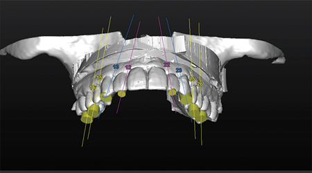
We propose here one alternative for planning the implant position. When using the vacuform our data showed that the transition line should be higher than the patient’s actual gingival line. Thus the study model was modified. Teeth are removed and trimmed down to the predicted desired transition line. After trimming the study model, a diagnostic wax up was prepared on that model. This wax up was then optically scanned and superimposed on the CBCT scan (Fig. 9). The teeth modifications are visible by superimposing the study cast to the diagnostic cast (Fig. 10). The integration of both the CBCT and diagnostic wax up enabled a critical analysis in guiding the 3D position of the implants at the time of surgery (Figs. 11 & 12).
Figure 9
A diagnostic wax up is prepared with the directive of reducing the verticalmaxillary excess by closing down the VDO. This will allow to contour the bone crest with osteoplasty and locate it more apically. Implants will be planned according to this diagnostic wax-up. Measurement from the tip of the incisor teeth are taken off the cast to coordinate the reduction of the VDO.
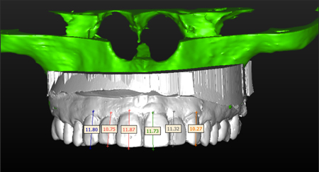
Figure 10
A superposition of the original diagnostic cast on the final wax-up depicts the modifications in the teeth positions. Redbeing the original diagnostic cast and white being the proposed diagnostic wax.
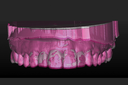
Figure 11
Implant planning is completed with the teeth diagnostic wax-up. Transparencyof the CBCT superimposed on the optical scan allows a reversed engineering process of implant positioning.
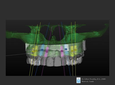
Figure 12
An occlusal 3D view of the planned implants positions in relation to the diagnostic wax-up, depicts the emergence profile of the implants exit position on the teeth.
Close attention is focused to ensure that all implants are at a distance from vital structures and don’t perforate or cause bony dehiscence’s (Fig. 15).
In this case study, immediate implants 18,19 were planned to be positioned in the bone furcation of the molars and in the bone triangle palatal to the incisors (Figs. 13 & 14). One must realize that inserting an implant into a bone furcation with a free hand can lead to a high risk of deviating from the planned scenario. Therefore, virtual planning with a surgical computer generated guide20 allows the surgeon to achieve a higher degree of precision that is seldom, if not impossible, achievable in free hand surgery. Otherwise it will be close to impossible to match the implant position to a pre-fabricated screwed prosthesis.
Figure 13
Posterior implants are located in the root furcation. This will allow a maximum anchorage of the implant for an optimal primary fixation.
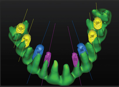
Figure 14
Implants are planned in the triangle space palatal to the incisors.

Figure 15
All implants are positioned into the bone. Notice no dehiscence or fenestration of any implants are perceived on this 3D reconstruction.

Based on the CBCT, bone density is evaluated around each implant to assess the possibility of having a minimal average requirement of 600 Hu for an immediately loaded implant (Fig. 16). Parallelism between the implants was verified with the parametric software to ensure that the prosthesis will fit on straight stock abutments (Fig. 17). A stereolithographic surgical tooth supported guide is then fabricated from this planning (Biomet 3I -Navigator, SimPlant-Materialise Dental, Dentsply, Belgium) (Fig. 18). The stereolithographic surgical guide was used as a template to fabricate a stone cast with implant analogues and a transitional fixed prosthesis (Figs. 19 & 20).
Figure 16
A density tool will give an evaluation of bone density at 1mm in periphery of the implant. Metrics are in Hounsfield Units. This evaluation will determine the possibility of immediately loading an implant.

Figure 17
This detailed figure includes: implants angulations, buccal to lingual, mesio-distal and rotations. These measurements will assure the parallelism between all implants. A maximum discrepancy of 14 degree is tolerated between implants for the use of stock abutments. In this scenario, a maximum of 12 degrees wasachieved between the most inclined implants; therefore stock abutments can be used to prepare an immediate bridge immediate.
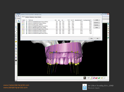
Figure 18
A surgical stereo lithographic tooth supported guide is ordered according to the 3D planning. This guide was used for immediate implant insertions and the preparation of a transitional immediate fixed prosthesis.

Figure 19
Implants and abutments are inserted on a cast and all remaining teeth are removed. Stock abutments are anchoredon the implants since less than 12 degrees of discrepancy is calculated between implants.

Figure 20
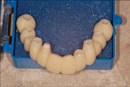
A one-piece acrylic immediate fixe prosthesis was prepared on the implant abutments.
Surgery
The patient was premedicated for surgery: Clydamicine (Missisauga, Ont., Canada), Dextrametasone (Advacare, Wilmington, DE, USA) and Ibuprofen (Advacare,
Wilmington, DE, USA ). In the planning process, two central incisors and two second premolars were left in their respective position for a tooth supported flapless stereolithographic surgical guide.21,22,23 Curetage of the granulation tissue in the alveolus was completed with an ultrasound device (Piezo surgery 3, Mectron, Italy) and used to debride all remnants of soft tissue in the implant recipient site.24 Piezosurgery was also used for a Regional Acceleratory Phenomenon.25 After implant placement, all remaining teeth were extracted. A total of eight dental implants were placed, four in the pre-maxillary zone and four in the posterior zone (Biomet 3I, Tapered implants, full osseotite, Canada) (Figs. 21 & 22). Particulate bone allograft (Mineros, Osteotech, Canada) mixed with platelet rich fibrin (PRF)26 was used to fill the voids around the implants and in the remaining alveolus. Soft tissue closure was achieved with interrupted suture (Gore-Tex, Gore & Ass., USA). Healing of the wound was by second intention. All implants were tested with Radio Frequency Analysis (Osstell, ISQ, Sweden) and torque tested to ensure the required clearance for immediate implant loading–a minimum of 65 for the RFA measurements and 40 Ncm for torque resistance.
Figure 21
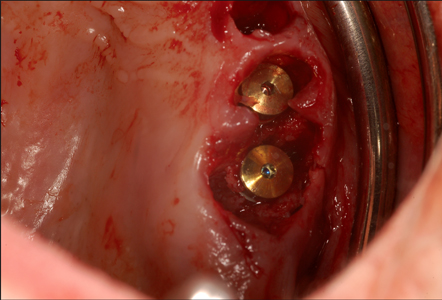
A flapless surgery with a tooth supported stereo lithographic surgical guide was completed. Notice that remaining teeth were extracted after completing implants insertions.

Figure 22
High precision implant insertion is achieved with computer-guided surgery. Flapless surgery and implants are inserted in the bone furcation without any deviation,hence primary fixation is achieved and prosthetic matching was completed. This surgical precision cannot be achieved with free hand surgery.
A PMMA one-piece screwed prosthesis bridge was prepared prior to surgery.
The computer generated surgical guide was used to create an in-lab study model on which analogues of the surgical implants were positioned. That model was articulated on an adjustable Panadent articulator (Colton, CA., USA). All abutment receptacles in the prosthesis were hollowed out with the exception of a single abutment in position (Fig. 20).1,2 This later unit will serve to seat the PMMA bridge exactly on top of the implant and simultaneously all the remaining housing in this PMMA bridge will be filled with a liquid composite (SmartCem2, Dentsply, Ont. Canada).
Hence, a one piece fixed maxillary transitional prosthesis was screwed into place (Figs. 23 & 24).28
Figure 23
Immediate temporary fixed prosthesis. Six-months post-op radiograph.
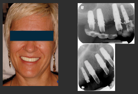
Figure 24
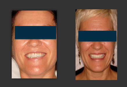
Before and after photograph. Final prosthesis is a zirconia to porcelain cemented restoration. Notice, as predicted, correction of vertical maxillary excess and positioning of the final transitional line under the superior lip.
Prosthetic Phase
Before starting the process of preparing the final prosthesis, an eight-month healing period was allowed to achieve oseointegration of the implants.
The temporary transitional prosthesis was used to evaluate the functional and aesthetic requirements for the eventual permanent prosthesis design. Soft tissue carving was also achieved from the anatomical profile of the temporary prosthesis. The transition line of the temporary prosthesis was evaluated for its position within the aesthetic zone in static and dynamic movements. Once patient satisfaction was achieved with her temporary transitional prosthesis, a final impression and bite records in maximum intercuspal position were recorded. An open tray technique was used to pick the impression up directly on the implant connections.
The impression model was then optically scanned and sent to Atlantis (Atlantis, Dentsply, USA) to manufacture CAD-CAM titanium abutments29 that were tailored for this case. The natural colour of titanium is of a grey scale appearance; coating the abutments with a gold alloy would reduce the visualisation of the abutment colour through the porcelain prosthesis. Zirconia substructures of all three prosthesis sections were CAD-CAM designed and milled from a solid zirconia block. Aesthetic design and vertical dimension of occlusion were reproduced from the temporary prosthesis. The zirconia framework was covered with porcelain for function and aesthetics and then cemented on the CAD-CAM abutments (Figs. 24-26). This new prosthesis was segmented into three sections; an anterior section that couples all pre-maxillary teeth from cuspid to cuspid, and two bilateral sections for the posterior implants. Separating the prosthesis in three parts will facilitate any prosthetic maintenance requirements.
Figure 25
Occlusal view. Notice implant emergence profile in conjunction with the final prosthetic design.
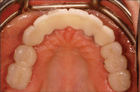
Figure 26
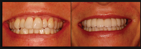
Before and after photographs.
Since the patient will eventually have all of their mandibular teeth removed and replaced by dental implants, all occlusal adjustments were executed on the mandibular dentition. An ideal maxillary crown morphology and design were achieved without compromise. After delivery of the maxillary prosthesis, a maxillary night guard was fabricated and adjusted for maximum cross-arch protection when the patient sleeps.
This patient was very satisfied with their maxillary rehabilitation treatment and is planning to go forward and restore her mandible with dental implants.
Discussion
Determining the transition line prior to tooth extraction requires multiple factors to be assessed. First, the bone crest profile must be carefully mapped in the 3D CT scan. In order to visualise this bone crest profile, virtual teeth extraction is required. Caution must be applied with the virtual teeth extraction tool on the CBCT. Bear in mind that the fine crestal bone around the teeth can be accidently removed virtually and as a result fail the goal of predicting the treatment. Furthermore, to achieve a predictable result during surgical teeth removal one must proceed with these extractions without altering the bone morphology to replicate the proposed plan. Deviating from the plan by removing too much bone during the extraction process will alter the prosthetic plan. Ideally, proceeding with a flapless tooth extraction using a periotome will increase the chances of maintaining intact crestal bone. One must bear in mind that the fine crestal bone is composed of cortical bone and little to no blood vascularisation provided by the bony structure.
Vascularisation of the fine cortical crestal bone will be provided from the buccal periosteum and the tooth’s periodontal ligament. Therefore, raising a full thickness flap and proceeding with tooth extraction will potentially deprive the crestal bone of its blood supply and cause crestal bone loss. However, we must be prepared for unplanned difficulties in the tooth extraction as root tips fracture, bone walls fracture, and soft tissue tears. In these complex cases a backup protocol must always be prepared in advance.
When using the vacushell for predicting the transition zone, this tool will allow clear visualization of the predicted soft tissue line of the patient in vivo during dynamic and static lip movements. The clinician must emphasize to the patient about executing extreme lip movements so as to ensure all records are attributed to her/his reality.
Once the diagnostic wax-up is completed, there is no way of verifying this diagnostic wax up in the patient’s mouth prior
to the surgery. To predict the wax up prosthetic plan in the patient’s mouth, the implants must be placed according to the wax up prosthetic plan by means of reverse engineering. The only predictable way is an optical scan of the prosthetic wax up, merge this optical scan to the CBCT scan, and then virtually place the implants in the corresponding position with a reverse engineered protocol. Hence a true reverse engineering process is achieved.
A stereolithography surgical guide allows one to proceed with a flapless surgery that will match the immediate prosthesis, otherwise it is close to impossible with free hand surgery to achieve such precision and adaptation to the immediate prosthesis.
Computer guided surgery has its share of limitations:
• Dimensional stability of the stone cast for guide preparation
• Movement and fit of the guide during surgery
• Mouth opening limitations of the patient
• Quality of the CBCT image acquisition
• Quality of the stereolithographic guide
• Challenge for determining the crestal bone
• Metal artefact that can affect planning and guide
fabrication
• Knowledge and experience of the operator on reading and planning off of a parametric software
Computer guided surgery has also its advantages:
• Achieving predictable flapless surgery
• Transparency of the stereolithographic guide that allows see through and visualization of the model
• Securing the implant in a precise position that takes in to account the remaining bone volume after tooth extraction
• Respecting vital structures and reduced iatrogenic
outcomes
• Placing implants in the molar’s bone furcation that otherwise with free hand surgery will be at a high risk of deviating from the furcation and not coordinating with the prosthesis
• Succeeding into matching the implant placement with the previously prepared immediate prosthesis made from a virtual plan
• Maintaining a straight osteotomy into a variable bone density column
• Truly reverse-engineer driven
• Reduced operatory time
• And finally, less invasive with flapless surgery, reduced post-op swelling, reduced post-op medication and increased patient comfort.30
Computer guided surgery will allow the patient to leave the operatory room with a precise screwed immediate prosthesis and have a predictable smile; this is clearly a benefit to the patient.
Conclusion
This case study demonstrated that it is possible to predict the transition line in the pre-maxilla prior to implant placement.
In this case report it was demonstrated that accuracy and precision in planning a complex dental rehabilitation case, that requires predictability in the aesthetic zone, can be accomplished by using an innovative scanning procedure as an alternative to intuitively driven treatment planning.
The use of an optical scan superimposed on a CBCT scan allows the clinician to visualise the patient’s clinical bone crest in the aesthetic zone and adapt the treatment plan to predict the transition line of the future prosthesis. The key to this procedure is that when properly performed, one can predict the patient’s future smile and deliver the prosthesis as initially planned.
Optical scans are traditionally used for dental restorations; this new approach definitely has its merits and a promising future in implant rehabilitation application. OH
Oral Health welcomes this original article.
Acknowledgement: It is important to underline the implication of Therese Lanciault M.Sc. from l’Institue d’Implantologie
Dentaire du Québec and Anas Raffoul from R & B Dental Labs, in the contribution of this original publication.
References
- Jivraj S. Chee W. & Corrado P. Treatment planning of the edentulous maxilla. British Dental Journal (2006);201, 261–279
- Mascarenha VI. Scaf de Molon R. Tavares LJ. Ferreira Mendes LM. Tonetto Mr. Celho Bandeca M. The use of computer guided implant surgery in oral rehabilitation : a literature review. World journal of dentistry, 2014;5(1): 60-63
- Oh TJ , Shotwell JL, Billy EJ, Wang HL. Effect of flapless implant surgery on soft tissue profile: a randomized controlled clinical trial. J Periodontol. 2006 May;77(5):874-82
- Saj Jivraj and Hooman Zarrinkelk. Graftless solutions in implant dentistry: Implants. 2012;Part 1.; vol 3; 8-19
- Trinkner Thomas F. The Role and Future of Botulinum Toxin in Dentistry. Journal of Cosmetic Dentistry. 2011: Vol 27, No. 1: 80-84
- Siva CO. Ribeiro-Junior NV. Campos TV. Rodrigues JG. Tatakis DN. Excessive gingival display: treatment by a modified lip repositioning technique. J Clin Periodontol. 2013 Mar; 40(3): 260-5
- Reetika Gaddale, Shrikar R. Desai, Jayashree A. Mudda, and Karthikeyan. Lip repositioning. J Indian Soc Periodontol. 2014 Mar-Apr; 18(2): 254–258.
- Kois JJC : Predictable single Tooth Peri-implant Esthetics : Five Diagnostic Keys. Compendium 2001;Vol. 22, No.3; 199-206,
- Kan Joseph Y.K. Roe Phillip. Rungcharassaeng Kitichai. Patel Rishi D. Waki Tomonori. Lozad Jaime L. Zimmerman Grenith. Calssification of Sagittal Root Position in Relation to the Anterior Maxillary osseous Housing for Immediate Implant Placement: A Cone Beam Computed Tomography Study. Omt. J. Oral & Maxillofacial Implant. 2011; Vol 26, No. 4:873-876
- Scott D. Ganz, The Reality of Anatomy and the Triangle of Bone, Inside Dentistry. 2006, June, Vol 2, Issue 5:
- Misch Carl E., Contemporary implant dentistry, 2nd edition, Mosby, 1999, p. 109
- Misch Carl E., Dental Implant Prosthetics, Mosby Inc., 2005, p 133
- Song Y-D, Jun S-H, Kwon J-J. Correlation between bone quality evaluated by cone-beam computerized tomography and implant primary stability. Int . Oral & Maxillofacial Implants, 2009, vol. 24, no 1,: 59-64
- Tatli U, Salimov F, Kurkcu M, Akoglan M, Kurtoglu C. Does cone beam computed tomography-derived bone density give predictable data about stability changes of immediately loaded implants: A 1-year resonance frequency follow-up study. J Craniofac Surg. 2014 May; 25(3):e293-9
- Fuster-Torres ma, Penarrocha-Diago M, Penarrocha-Oltra D, Penarrocha-Diago M. Relasionships between bone density values from cone beam computed tomography, maximum insertion torque, and resonance frequency analysis at implant placement: a pilot study. Int J Oral Maxillofac Implants. 2011 Sep-Oct; 26
(5): 1051-6 - Pinheiro ottoni J M, Lima Oliveira Z F, Mansini R, Melo Cabral A. Correlation between placement torque and survival of single-tooth implants. Int. Journal of Oral & Maxillofacial Implants, 2005, vol.20, no5, p.769-776
- Capelli M, Zuffetti F, Del Fabbro M, Testori T Immediate rehabilitation of the completely edentulous jaw with fixed prostheses supported by either upright or tilted implants: a multicenter clinical study. Int J Oral Maxillofac Implants. 2007 Jul-Aug;22(4):639-44
- Malo. Rangert. Dvarsater. Immediate function of Branemark implants in the esthetic zone: a retrospective clinical study with 6 months to 4 years of follow-up. Clin Oral Impl Rel Res 2000; 2:137-145
- Norkin Frederic J. Ganeles Jeffrey. Sekler Julio. Zfaz Samuel. Immediate Loading of Endosseous Dental Implants: A Review of the Evidence. Inside Dentistry. 2008; April Volume 4, Issue 4
- Farley N E. Kennedy K. McGlumphy EA. Clelland N. Split mouth comparaison of the accuracy of computer generated and conventional surgical guides. Int. J of Oral and maxillofacial implants. 2013;28:563-572.
- Manikandan Ramasamy. Giri. Ramesh Raja. Subramonian. Karthik. and Rachuri Narendrakumar. Implant surgical guides: From the past to the present J Pharm Bioallied Sci. Jun 2013; 5(Suppl 1): S98–S102.
- Gillot Luc. Cannas Bernard. Friberg Bertil. Vrielinck Luc. Rohner Dennis and Pettersson Andreas. Accuracy of virtually planned and conventionally placed implants in edentulous cadaver maxillae and mandibles: A preliminary report. J. of Prosthetic Dentistry. Oct 2014. Volume 112, Issue 4, Pages 798–804
- Abboud M, Wahl G, Guirado JL, Orentlicher G Application and success of two stereolithographic surgical guide systems for implant placement with immediate loading. Int J Oral Maxillofac Implants. 2012 May-Jun;27(3):634-43
- Blus C, Szmkler-Moncier S., Atraumatic tooth extraction and immediate implant placement with Piezosurgery: evaluation of 40 sites after at least 1 year of loading. Int J Periodontics Restorative Dent. 2010 Aug;30(4):355-63
- Blus C1, Szmukler-Moncler S, Khoury P, Orrù G Immediate implants placed in infected and noninfected sites after atraumatic tooth extraction and placement with ultrasonic bone surgery. Clin Implant Dent Relat Res. 2015 Jan;17 Suppl 1:e287-97. doi: 10.1111/cid.12126. Epub 2013 Jul 30.
- Misch Carl E., Dental Implant Prosthetics, Mosby Inc., 2005, p 340
- Barry I. Simon, Priyu Gupta, Shereen Tajbakhsh. Quantitative Evaluation of Extraction Socket Healing Following the Use of
Autologous Platelet-Rich Fibrin matrix in Humans. Int. J. Periodontics & Restorative Dentistry. 2011; Vol 31, 3: 284-295 - Maló P, de Araújo Nobre M, Lopes A, Ferro A, Gravito I Complete Edentulous Rehabilitation Using an Immediate Function Protocol and an Implant Design Featuring a Straight Body, Anodically Oxidized Surface, and Narrow Tip with Engaging Threads Extending to the Apex of the Implant: A 5-year Retrospective Clinical Study. Int J Oral Maxillofac Implants. 2016 Jan-Feb;31(1):153-61.
- Kapox T. Evans C. CAD/CAM Technology for Implant Abutment, Crowns, and Superstructures. Int. J. Oral & Maxillofacial Implants. 2014: Vol. 29, Supplement: 117-136
- ArisanV, Bloukbasi N, Oksuz L. Computer-assisted flapless implant placement reduces the incidence of surgery-related bacteremia. Clinical oral Investigations (2013)
 Dr. Gilbert Tremblay, B.Sc., D.M.D., Diplomate of the American Board in Oral Implantology/ID, Diplomate of the International Congress in Oral Implantology, Fellow of the American Academy in Implant Dentistry, Private practice in Montreal-Canada,President of the Quebec Dental Implantology Institute.
 Dr. Reginaldo Goncalves is a board certified specialist in periodontics, a Fellow of the Royal College of Dentists of Canada and a Diplomate of the American Board of Periodontology. He is the Director of thePeriodontics Graduate Program at Laval University.
RELATED ARTICLE: Implant Dentistry for Complete Maxillary Rehabilitation: Two Innovative Protocols
Follow the Oral Health Group on Facebook, Instagram, Twitter and LinkedIn for the latest updates on news, clinical articles, practice management and more!


