Introduction
This case report will discuss a staged approach for the delivery of implant therapy in the upper anterior jaw. A crown-down surgical approach was used to help determine the ideal prosthetic location for implant placement. Cone beam CT imaging was utilized to visualize the available volume of bone. Treatment was delivered in stages, to maximize the chance of achieving a successful and stable long-term esthetic result.
Implant dentistry involves a team approach. Often the team includes the orthodontist, the restorative dentist, the dental technician, and the implant surgeon. When there are four bright minds working together, treatment planing, and carrying out the treatment, the patient benefits tremendously, and their satisfaction will reverberate over and over, back to each clinician’s respective practice. It is important to understand the skill level of each member of the team. This way, communication becomes far easier, and the common goal of having a successful result and a satisfied patient will be reached with a higher degree of predictability.
Next, it is important to identify the complexity of the case that you are treatment planning, so that you have a good idea of the steps that are involved. Presented in Figure 1 is a table of some of the factors that affect the success of implant therapy. 1
Figure 1

It is important to be able to get to know your patients, and understand their chief concern, what level of treatment complexity they are willing to undertake with, how much time they are willing to commit, and what their financial limitations are. When planning implant therapy in the esthetic zone, it is important to know when you can and cannot compromise. A patient may be mid-way along a treatment plan, which includes pre-operative orthodontics, hard and soft tissue grafting, implant placement, provisionalization, and then final restoration. They may decide midway that they cannot wait any longer, and that they just want to get to the final result. As clinicians, we need to hold our ground, stick to our principles, and educate our patient about why they need to commit to the treatment effort.
Crown-Down Surgery Approach
A restoration-driven implant placement protocol in anterior maxillary sites requires optimal three-dimensional implant positioning in the edentulous site, whereby the implant is thought of as an apical extension of the ideal future restoration. This will ensure the best probability of having a successful and long-lasting esthetic treatment outcome. The three different planes of space: coronal, sagittal, and transverse should be considered (Fig. 2).
Coronal Plane
In the coronal plane, we need to consider the correct vertical positioning of the implant. The final implant shoulder sink depth for an esthetic fixed single implant crown is determined by the location of the cement-enamel junctions (CEJs) of the neighbouring teeth, and by the level of the free gingival margins on the facial aspect of the same teeth. In the case shown (Fig. 3), the facial CEJ and facial free gingival margins of teeth 11 and 22 happen to be on the same level, because these teeth do not have any gingival recession. The implant shoulder should be positioned 2 mm apical to a line (in blue) connecting these two points. 2
Figures 2 and 3
Three planes of space to consider in a crown-down surgery approach. Implant shoulder should be 2mm apical to the CEJ/facial gingival margin of the neighbouring teeth.

This same 2 mm rule (in blue) has now been transposed onto a dental radiograph (Fig. 4). Interproximal bone adjacent to the implant site will provide essential support for the overlying soft tissue papilla. The interproximal bone needs to be at a distance of ≤2 mm from the interproximal CEJs (in green). 2
Figure 4
Interproximal bone should be less than 2mm apical to the CEJ to provide essential papilla support.

Figure 5 shows pre- and post-operative clinical photos and radiographs of the site, with failing endodontic treatment on tooth 21, which has caused severe buccal alveolar ridge resorption. Interproximal bone remains intact, however, with corresponding full soft tissue papilla fill. This bone was largely retained throughout the treatment process, resulting in almost-complete papilla fill after the final restoration.
The treatment objective in the case of an anterior single tooth replacement is to have an implant-supported crown with a gradually developed flat emergence profile (in red), from the implant shoulder to the peri-implant mucosal margin (Fig. 6). Ideally, the clinical implant-supported crown should replicate the clinical crown of the corresponding contralateral tooth, from the line of the soft tissue emergence, to the incisal border. 3
Figure 5
Preserving papilla height by maintaining interproximal bone post-treatment.
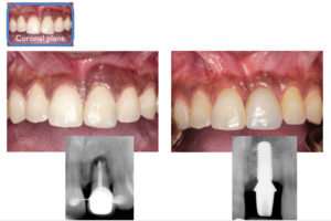
Figure 6
Planning for a gradually developed, flat emergence profile.

Sagittal Plane
The axial profile of the implant restoration can be visualized in the sagittal plane (Fig. 7). On the left is a pre-operative cone beam CT view of the natural maxillary central incisor, tooth 21, and on the right is the simulated future implant-supported crown. After loss of the tooth, there will be an expected decrease in alveolar ridge width and height. Even after advanced guided bone regeneration (GBR), the implant will still need to be placed in a more palatal position, when compared to the original root position. This in turn will influence the axial profile of the implant restoration (in red). The intent of grafting is to allow placement of the implant as close to the original root position as possible, so that we can have a gradually-developed, flat axial profile for the final implant-supported crown.
Figure 7
Planning for a gradually developed, flat axial profile.

Transverse Plane
In the transverse plane, which is essentially an occlusal view of the implant, the implant surgeon needs to identify the axis of the implant which is most compatible with the prosthetic plan (Fig. 8). Ideally the implant axis should be identical with the prosthetic axis.
Figure 8
Planning for an implant axis that is identical with the prosthetic axis.

Patient Profile
The case presented is a healthy 26-year-old female, who had a history of trauma to the upper left central incisor 10 years prior to presentation (Fig. 9). Since then she received endodontic treatment for this tooth, and later on retrograde apicoectomy surgery. Retreatment was not successful, and the patient was referred to consider implant therapy to replace this tooth. She had an otherwise healthy periodontium. Of note is the buccal cross-bite which is present in the bilateral posterior segments. The patient had a low smile line.
Patient Concerns
The patient’s main concern was that she needed to replace her upper front tooth with something that would last for the rest of her life. She also wanted to have a treatment outcome that looked as natural as possible.
Diagnosis
At presentation (Fig. 9) the patient had a healthy periodontium, with failing endodontic treatment on tooth 21. Tooth 21 had a hopeless prognosis. There was a Seibert Class III alveolar ridge deficiency, with a slight loss of ridge height, but a large loss of ridge width (Fig. 10). The CT scan showed a complete loss of the buccal alveolar plate.
Figure 9
Clinical presentation.

Figure 10
Initial CBCT image.

Treatment Recommendations
Extraction and either implant therapy, or a fixed bridge was recommended and discussed. Implant therapy would proceed in stages, starting with extraction, then GBR, implant placement, provisionalization, and then a final crown would follow. The patient understood that implant therapy involved multiple visits, spread out over one year. She was also made aware that no matter what we did, we could not guarantee retention and maintenance over time of the full height and contour of the pre-operative interproximal papilla. Informed consent was obtained.
Surgical Treatment
Tooth 21 was extracted, followed by a waiting period of one-month to allow for complete soft tissue closure over the socket. The site was then re-entered with a large access flap (Fig. 11). Any remaining infected granulation tissue was removed and the socket was debrided; the full extent of the defect was visualized. A Class III ridge deficiency was confirmed (Figs. 12-13). Multiple cortical perforations were made to enhance blood supply to the graft (Fig. 14). The site was then grafted with particulate bone graft, and reinforced with titanium meshwork stabilized with three retaining tacks (Fig. 15). The meshwork was covered with a resorbable collagen membrane (not shown). The surgical site was closed using a combination of chromic gut absorbable suture for the vertical releasing incisions, and monofilament poly-tetra-fluoroethylene non-absorbable suture for the mid-crestal incision. Cyanoacrylate oral adhesive was placed over-top the gingival flap margins to minimize post-operative tissue recession. An Essix appliance was inserted to replace the missing tooth (Fig. 16).
Figure 11
GBR access flap.

Figure 12
Ridge deficiency facial view.

Figure 13
Ridge deficiency occlusal view.

Figure 14
Cortical perforations to enhance blood supply to the graft.

Figure 15
Graft secured with titanium meshwork.

Figure 16
Site closure and insertion of Essix appliance.

One month later, all remaining sutures were removed and the patient’s original tooth, with root removed, was re-splinted in place, this time completely out of occlusion in order to avoid any trauma to the grafted site (Figs. 17-18).
Figure 17
One month post-operative facial view with splint.

Figure 18
One month post-operative occlusal view with splint.

Healing proceeded uneventfully. A small portion of the meshwork had become exposed at six months post-operative. The splint was removed to fully visualize and inspect the site (Figs. 19-20). No infection was suspected. The splint was re-cemented, and the patient was prescribed a chlorhexidine 0.12% rinse and chlorhexidine 0.25% gel for topical application to the exposed mesh until the time of implant placement.
A pre-operative and six-month post-graft comparison can be seen in Figure 21. The GBR procedure was successful. The regenerated ridge was wide enough to support the placement of a 4.1 mm diameter Straumann Bone Level implant.
The site was re-entered at seven months post-grafting. The meshwork was removed, and the graft appeared fully vital. There was no sign of infection (Figs. 22-23). The ridge at the implant site was scalloped in a U-fashion (green lines) to mimic its natural shape. The alveolar crests at the adjacent teeth were not touched. This procedure, along with the use of a surgical stent, helps to visualize and plan for optimal implant positioning (Figs. 24,25).
Figure 19
Six month post-operative facial view with splint removed.

Figure 20
Six month post-operative occlusal view with slight exposure of meshwork.

Figure 21
Pre-graft and post-graft comparison.

Figure 22
Meshwork before removal.

Figure 23
Graft exposure.

Figure 24
Scalloping of osteotomy site.

Figure 25
Osteotomy site development using surgical stent.

A Strauman Roxolid SLActive Bone Level implant was placed. The implant was positioned such that at least 1mm of alveolar ridge remained on its buccal aspect, to minimize peri-implant soft tissue recession. A small dehiscence at the alveolar crest was re-grafted with particulate bone graft. This graft was covered with a resorbable collagen membrane before site closure. An Essix appliance was inserted again to replace the missing tooth (Figs. 26-31). A prosthetic tooth 21 was re-splinted at one-month post-operative.
The implant was uncovered after a three-month integration period, and the splint was replaced. The peri-implant mucosa was allowed to heal for one-month before provisionalization (Figs. 32-34).
Figure 26
Strauman Roxolid SLActive Bone Level implant.

Figure 27
Implant placement with attention to buccal ridge dimension.

Figure 28
Small dehiscence at alveolar crest re-grafted with particulate bone.

Figure 29
Site closure.

Figure 30
Insertion of Essix applicance.

Figure 31
Implant placed with cover screw.

Figure 32
Implant uncovery and replacement of splint.

Figure 33
Radiograph of uncovered implant.

Figure 34
Healing of peri-implant mucosa one month after uncover.

Prosthetic Treatment
A timeline of the provisionalization process is shown in Figure 35. The peri-implant mucosa needs at least three months to stabilize and mature around the provisional crown. It has been suggested that in order to maximize the full potential of a provisional crown, that the patient return twice after placement of the provisional so that the crown can be re-adjusted and re-contoured, before the final impression.
Figure 35
Timing of implant provisionalization.

The benefits of provisionalization are that it allows us a chance to maximize the emergence and axial profiles of the peri-implant mucosa. It also allows the restorative dentist and the implant surgeon a period of time within which to observe tissue levels, and see how much natural re-growth of inter-dental papilla occurs. The major benefit is that it provides for a staged and conservative approach, and in some cases it may eliminate the need for any further surgical soft tissue augmentation. In addition, provisionalization allows us to manage our patient’s expectations early in terms of the shape and shade of the restoration, before the final crown is fabricated. Finally, it allows us to register this well-developed sulcus using a custom impression coping, and then communicate these findings to the dental laboratory technician, along with the final impression. 4
A cement-retained provisional crown was fabricated one-month after implant uncovery, after successful osseointegration had been verified. A Strauman Regular Crossfit VITA CAD Temporary Abutment was used. This is essentially a tooth-coloured poly-methyl-methacrylate polymer that is cured directly onto a titanium abutment. This abutment allows for easy and quick chair-side modification. A radiograph was taken to verify full seating of the abutment. The abutment was prepared, just as if it were a regular tooth crown. The screw-channel access was blocked with gutta percha, and an Ion crown form was retrofitted onto the temporary abutment using Duralay. Pink opaquer was cured onto the facial aspect of the crown to mimic the pattern of the adjacent incisor. The crown was adjusted out of occlusion (Figs. 36-39). The patient returned for re-adjustment and re-contouring of the provisional crown before the final restoration three months later.
Figure 36
Insertion and preparation of temporary abutment.

Figure 37
Extraoral view of the temporary abutment.

Figure 38
Provisional implant crown inserted and adjusted out of occlusion.

Figure 39
Radiograph taken to verify full seating of the temporary abutment.

Five factors should be considered for maximizing esthetic success, when selecting the final restorative abutment: 1) three-dimensional implant placement for functional and esthetic long-term success, 2) sufficient soft tissue thickness to conceal the implant-restorative interface, 3) selecting an abutment that satisfies biocompatibility, tissue stability, colour, translucency and fluorescence, 4) a crown restoration that imitates the contralateral tooth, and 5) the patient’s lip line. 5
Zirconium oxide abutments are extremely popular because they are known to have high flexural strength, are biocompatible, allow for full control of the emergence profile and cement line, and allow achievement of ideal colour, translucency, and esthetics. This final implant crown was fabricated with a zirconium oxide core, with PolyDent Dental Ceramic Laboratory, and the registered dental technician was Gus Tserotas (Figs. 40-42). The implant surgeon and provisional restorative dentist was the author. The final restorative dentist was Dr. Tudor Dabuleanu.
Figure 40
Final abutment made out of zirconium oxide.

Figure 41
Seating of the final abutment.

Figure 42
Provisional and final implant crowns with radiograph.

Figure 42 shows a direct comparison of the peri-implant mucosa surrounding the provisional (left) and final (right) implant-supported crowns. During this three-month period there had been no re-growth of the inter-dental papilla on the mesial aspect of the implant, however a minor re-growth of the papilla had occurred on the distal aspect.
Conclusion
This case report discussed a staged approach for the delivery of implant therapy in the upper anterior jaw. A crown-down surgery approach was used to help determine the ideal prosthetic location for implant placement. Cone beam CT imaging was used to visualize the bone that was available, before and after a GBR procedure. Treatment was delivered in stages, to maximize the chance of achieving a successful and stable long-term esthetic result. Through good communication and with a teamwork approach, the restorative dentist, the dental technician, and the periodontist can work together to achieve a good result. OH
Dr. Valentin Dabuleanu maintains a private practice in Toronto limited to periodontics and implant surgery, in a combined endodontic and periodontal practice with Dr. Mary Dabuleanu, Endodontist, and alongside the family practices of Dr. Tudor Dabuleanu and Dr. Emilia Nicola, General Dentists. Dr. Valentin Dabuleanu is a Fellow of the Royal College of Dentists of Canada in Periodontology. He obtained his DDS from the University of Toronto in 2010, and subsequently completed a one-year general practice residency at Vancouver General Hospital. Dr. Dabuleanu completed his MSc degree and speciality training in Periodontology at the University of British Columbia in 2014. Dr. Dabuleanu can be reached at valentindab@gmail.com.
Oral Health welcomes this original article.
References
1. Buser D, et al. editor. ITI Treatment Guide – Vol. 1 – Implant Therapy in the Esthetic Zone – Single Tooth Replacements. Berlin: Quintessence; 2007.
2. Belser UC, et al. Prosthetic management of the partially dentate patient with fixed implant restorations. Clinical Oral Implants Research. 2000; 11 (Supp): 126-145.
3. Lindhe J, editor. Clinical Periodontology and Implant Dentistry. 5 ed. Oxford: Blackwell Munskgaard; 2008.
4. Priest G. A restorative protocol for implants replacing adjacent maxillary central incisors in a compromised site. Journal of Implant and Reconstructive Dentistry. 2009; 1: 13-18.
5. Gamborena I, & Blatz MB, editors. Evolution – contemporary protocols for anterior single-tooth implants. Hanover Park: Quintessence; 2015.
6. Foong JKW, et al. Fracture resistance of titanium and zirconium abutments: an in vitro study. Journal of Prosthetic Dentistry. 2013; 109: 304-312.