Introduction
In patients with inadequate ridge dimensions, the successful placement of dental implants is a challenge with regards to maintaining an ideal 3D positioning of the implant fixtures. Vertical and/or horizontal ridge augmentation procedures may be necessary using a combination of biomaterials to achieve this objective. Effective one-wall reconstruction of the posterior mandible has been challenging to many clinicians due to the inability to mobilize adequate soft tissue for passive primary closure and proper graft stabilization. The most important consideration is to minimize complications through principle-based ridge augmentation surgery.
Many surgical techniques have been documented to repair severe alveolar bony defects for dental implants. The clinician should aim to achieve ideal and clinically satisfactory results with appropriate techniques. The ideal technique should be simple, minimally invasive, and exhibit less risk of complications.1 Ridge augmentation is very technique sensitive and depends on the operator’s surgical training and proficiency.
This article will feature a case of a vertical and horizontal ridge augmentation technique for a patient with missing posterior teeth in the left lower mandible.
Case Report:
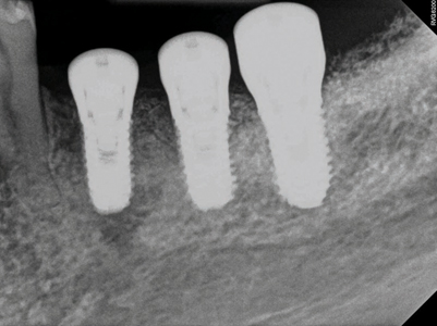
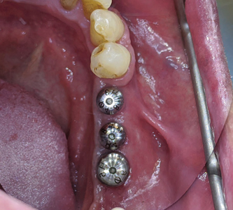
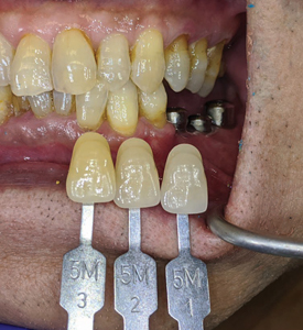
A healthy ASA 1, 80-year-young male patient had been referred by his family dentist to the office with complaint of missing lower left posterior teeth (Figs. 1 and 2). The patient presented with difficulty in eating and unable to chew his food to nourish himself. Due to his age, a detailed assessment was performed with a non contributory medical history having no contraindications for dental surgery. Patient is a non smoker and has no other social habits that would contravene dental surgery. His dental history provides information that he had lost his lower posterior teeth due to fractured endodontically treated teeth that supported 3 unit fixed bridges many years ago. He had dental implants done overseas in the quadrant 3 done about 3 years ago that had recently failed. Radiographs from the hygienist reveals a 3 unit implant bridge with an unfavourable cantilever on the 35 region (Fig. 3). The patient wanted to rehabilitate his left lower posterior teeth first to help with his eating needs (Fig. 4).
Fig. 1
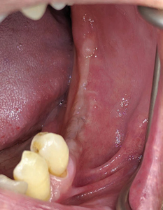
Fig. 2

Fig. 3
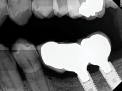
Fig. 4

After a detailed dental assessment and discussion with the patient about the risks, benefits and alternative tooth replacement solutions – the patient agreed upon the treatment plan that involved advanced hard and soft tissue regenerative procedures and the placement of dental implants to help rehabilitate his missing teeth.
Treatment plan
(3 surgical stages, 1 restorative)
- Reconstruct alveolar ridge in the 35, 36 and 37 region with titanium re-inforced PTFE membrane and a combination of autograft, allograft and xenograft
- Placement of implants in the 35, 36 and 37 region
- Mucogingival surgery to reduce frenal pull, deepen vestibular depth and improve amount of keratinized gingiva in the region
- Restore the implants with a screw retained, splinted, PFM restoration
- Deliver a soft splint night guard to protect the restorations
Surgical procedure (Stage 1)
Pre-surgical antibiotics were prescribed, Amoxicillin 2grams, 1 hour prior to the surgery, and to continue three times a day for the next 10 days.
Ibuprofen 400mg, 1 tablet, 1 hour prior to surgery and to continue 1 tablet every 4 to 6 hourly for 3 to 5 days with food.
Chlorhexidine 0.12% was prescribed as a mouth rinse for 2 weeks post surgery.
Pre-surgical preparation (patient was advised to brush his teeth, scrap his tongue thoroughly and rinse for 30 seconds with a cup of 0.12% chlorhexidine gluconate), local anaesthesia with 2% lidocaine and 1:100,000 epinephrine was administered as an inferior alveolar nerve block, lingual and long buccal nerve block with two carpules for the quadrant 3.
A full thickness flap was raised, and with the site fully exposed, pathological and inflammatory tissue were debrided from the socket of the failed implant in the 36 region and the site rinsed with a sterile saline solution. The extent of the ridge defect could be appreciated well in the 35 and 36 region (Fig. 5). Decortication of the site was done using a half size round surgical carbide utilizing a surgical HP with sterile saline (Fig. 8). A rotary bone collector (Fig. 6) was used to harvest some autogenous bone scrapings (Fig. 7) from 37 region and the site distal to it. The next most important step in the surgical procedure is to gently raise the lingual flap (Fig. 9) to allow for passive and adequate primary closure for the vertical / horizontal GBR procedure. A periosteal elevator is used to gently tease and pull in a coronal direction the retromolar pad tissue (Zone 1) (Fig. 10). This region is elastic and needs to be incorporated into the lingual flap release to allow for adequate tissue mobility. Once the lingual flap has been elevated adequately and allowing for visualization of the mylohyoid muscle, a blunt and wide elevator is used to gently push away the flap in a lingual direction allowing for the superficial separation of the muscle fibres (Zone 2). Care and precaution should be practised while separating the lingual fibres in the premolar region (Zone 3) due to deeper positioning of the muscle attachment (Fig. 11). Once adequate tissue mobility has been achieved, the use of a titanium re-inforced PTFE membrane is trimmed and secured utilizing 1.5 x 3.0 mm fixation screws on the lingual wall (Fig. 12). A composite graft (mixture of autogenous, allograft and xenograft particulates) (Fig. 13) is placed onto the defect (Fig. 14) and consolidated within the extents of the membrane and secured. Primary closure was attained with 4-0 PTFE and 5-0 Chromic gut sutures (combination of horizontal mattress and simple interrupted sutures) achieving passive flap adaptation and tissue eversion (Fig. 15). A panoramic radiograph was taken post surgery to evaluate position and volume of biomaterials with he PTFE membrane in place (Fig. 15A). The patient was comfortable and co-operative during the procedure, post surgical instructions were given and medication protocol reinforced.
Fig. 5

Fig. 6

Fig. 7

Fig. 8

Fig. 9

Fig. 10

Fig. 11
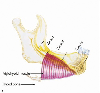
Fig. 12

Fig. 13
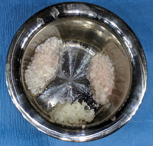
Fig. 14

Fig. 15

Fig. 15A

A 14 day follow up with suture removal reported healing without incidence, without untoward pain, signs of infection, oedema, nor perforation of the soft tissue not exposing any part of the PTFE membrane. A second post op review was done at 8 weeks with complete soft tissue healing and no signs of inflammation or infection.
The site was allowed to heal for a period of 9 months, whereafter the patient was recalled for pre-implant assessment (Figs. 16 & 17). Impressions (Fig. 18) were made to fabricate an anatomic wax up (Fig. 19) and a surgical pilot guide (Fig. 20) for the placement of the implants free hand in the sites 35, 36 and 37.
Fig. 16
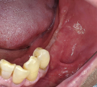
Fig. 17

Fig. 18

Fig. 19
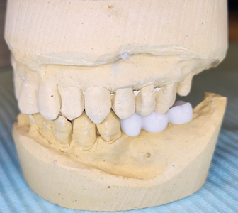
Fig. 20

Stage 2 surgical procedure:
Following pre-medication and pre-surgical protocols as described in stage 1 surgery, local anaesthesia with 2% lidocaine and 1:100,000 epinephrine was administered as inferior alveolar nerve block, lingual and long buccal nerve block with two carpules for the quadrant 3. A midcrestal incision was given with a 15c blade extending from the distal of the 34 unto the distal of the 37 region with a disto-oblique release incision. A full thickness flap was elevated revealing the underlying Ti-reinforced PTFE membrane. A gentle use of Lucas curettes and Molt periosteal elevators to reflect the non-resorbable membrane exposing the newly augmented bone (Fig. 21). Careful elevation of the lingual flap is performed (Fig. 22) with complete removal of the membrane and fixation screws (Fig. 23). Clinical inspection of the regenerated ridge appears to be well contoured and acceptable for the optimal 3D placement of dental implants (Fig. 24). The surgical pilot guide is used for the initial osteotomy (Fig. 25) prepared at 2.2 dia and 7mm depth. Guide pins secured to dental floss are then placed into the osteotomy sites (Fig. 26) and a radiograph is taken to verify its position to the underlying inferior alveolar canal and mental foramen (Fig. 27). Based on the guide pin parallelism and depth with appropriate safety distance to the IAN canal, final osteotomies are prepared as per protocol and tissue level implants (Fig. 28) were placed achieving primary stability at 35Ncm. Corresponding healing abutments (Fig. 29) were hand tightened and tissue closure was performed using 5-0 Vicryl with simple interrupted sutures (Fig. 30). A final radiograph was taken to evaluate positions of the implants (Fig. 30A). A 2 week follow up with uneventful healing was observed.
Fig. 21

Fig. 22

Fig. 23
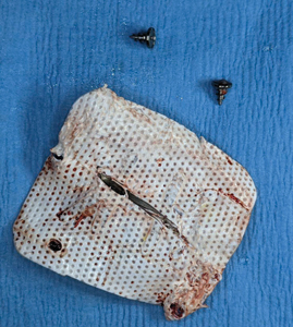
Fig. 24
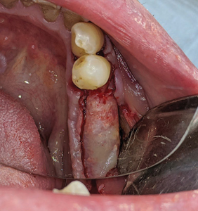
Fig. 25

Fig. 26
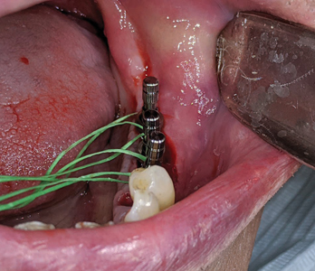
Fig. 27
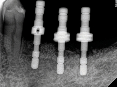
Fig. 28
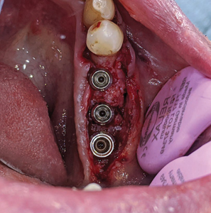
Fig. 29

Fig. 30
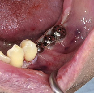
Fig. 30A
Stage 3 surgical procedure
After 2 months of implant placement (Fig. 31), the patient was called in for the 3rd and final procedure based on his surgical treatment plan. Due to his advanced age, thiner palatal tissue thickness and pain from tissue harvesting / donor site, a free gingival graft was not proposed, but instead a simple apically repositioned flap (Fig. 32) and the use of a porcine derived collagen matrix (secured with 5-0 Chromic gut sutures) was used to help correct the mucogingival deformity (increase tissue biotype with more keratinized mucosa) (Fig. 33).
2 week and 2 month follow ups were done with uneventful healing (Fig. 34).
Fig. 31
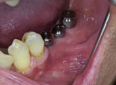
Fig. 32

Fig. 33

Fig. 34
Prosthetic phase
At 5 weeks following soft tissue surgery, the healing abutments were removed (Fig. 35) – the implant platforms were irrigated with 0.12% chlorhexidine and open tray impression copings (Fig. 36) were placed, hand tightened and verified with a periapical radiograph. A custom acrylic tray (Fig. 38) with heavy and light PVS impression material was used to impress the implants with a direct pick up impression technique (Fig. 39).
Fig. 35

Fig. 36
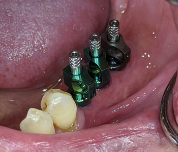
Fig. 37
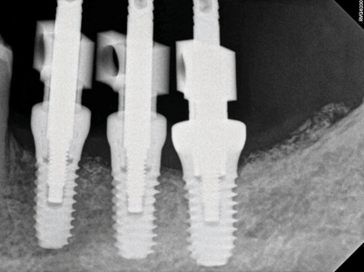
Fig. 38

Fig. 39

A metal try in (Fig. 40) was performed to verify passivity of the framework (Fig. 41) with a single screw and a radiograph to confirm optimal seating with all 3 implant platforms (Fig. 42). A rigid bite registration material was made intraorally and is used to help the technician double check the interocclusal restorative space (Fig. 43) and allow for adequate mounting on the articulator especially in this case scenario of multiple missing teeth in the distal end bilaterally of the mandibular arch. Photographs with multiple shade tabs (Fig. 44) were used to assist with layering the porcelain for the final screw retained prosthesis.
Fig. 40
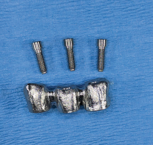
Fig. 41
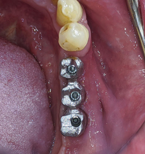
Fig. 42

Fig. 43
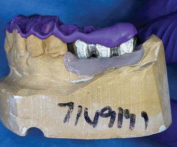
Fig. 44
A 3 unit screw retained PFM non hexed splinted restoration (Fig. 45) was finally delivered to the patient following implant insertion protocols (Fig. 47) with radiographic verification (Fig. 48) and final torqued at 30Ncm. The screw access holes were sealed with teflon and composite with custom stains were added. Proximal contacts and occlusion was verified and adjusted. The patient was satisfied with the final outcome and esthetics. He was referred back to see his family dentist for the fabrication of a soft splint night guard.
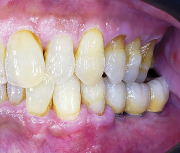
A 2 year follow up of the patient and its implant restorations show stable soft and hard tissues around the implant fixtures (Figs. 49 and 50).
Fig. 45

Fig. 46

Fig. 47

Fig. 48

Fig. 49
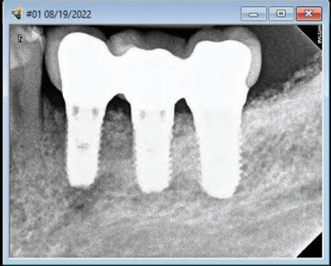
Fig. 50
Discussion
The successful treatment of vertical and horizontal bony defects has always been a real clinical challenge for most clinicians. An alveolar ridge deficient in volume to accommodate dental implants, or implant fixtures not ideally placed in the buccofacial manner, will cause tissue recession, loss of aesthetics, and eventual treatment failure. The posterior mandible represents an anatomical area where often complications arise due to insufficient knowledge of the anatomy and clinicians who lack adequate training and surgical expertise.
Schropp and al. 20032 evaluated the changes happening after teeth extraction by radiographic evaluation and by comparison of the stone casts before and after. Surprisingly data had reported volumetric variations with tissue loss reaching up to 50% of the original bone shape. The manner in which the bone in this region atrophies manifests as one of the reasons why there is such a high percentage of failure in this area.3 Esposito and al 20094 after a systematic review done on behalf of Cochrane, suggested the use of short implants in the posterior resorbed mandible noting that complications are a frequent finding in these areas.
Many surgical techniques have been introduced over the years and one among them most commonly practised was the use of ti-reinforced PTFE membranes. The use of PTFE membranes proved to be very tricky and their early exposure one of the weak links of the technique. Fontana and al. 2011 described seven different kind of complications, four in the healing phase based on the degree of exposure and exudate and three surgical (flap damage, neurological and vascular).5
In 2014 Urban et al.6 reported an average gain of 5.45 mm (sd. 1.93) on 19 patients treated with this technique for vertical ridge augmentation utilizing the combination of bovine derived anorganic bone with autogenous bone chips and the use of titanium reinforced dense PTFE membranes.
To achieve successful GBR the clinician needs to select techniques and materials that will create these three essential factors:1 Graft stability,2 Space maintenance,3 Support the blood supply. Neovascularization of a healing wound is paramount to its recovery and rehabilitation.7 A supported blood supply into graft material, be it autogeneic, alloplastic or xenogeneic, is critical for populating the site with osteoprogenitor cells, fibroblasts and leukocytes with their associated growth and chemotactic factors, and for an uninterrupted oxygenation and nutrient supply to the healing tissues.8 The technique as described by Simion9 and Urban10 fulfills the above mentioned criteria and has proven to be a successful surgical approach in vertical and horizontal regeneration of alveolar ridges in the posterior mandible.
Conclusion
Vertical and horizontal ridge augmentation has become a major and routine treatment option to provide optimal bone support for osseointegrated dental implants. Advanced GBR techniques when successfully applied in the posterior mandible can provide sufficient support for the replacement of multiple missing teeth with dental implant restorations. Based on current literature it can be
concluded that vertical GBR can be predictably achieved using non resorbable titanium reinforced PTFE membranes.
Oral Health welcomes this original article.
References
- Chiapasco M, Casentini P, Zaniboni M. Bone augmentation procedures in implant dentistry. Int J Oral Maxillofac Implants. 2009;24(Suppl):237–59.
- Schropp L, Wenzel A, Kostopulos L, Karring T. Bone healing and soft tissue contour changes following single-tooth extraction: a clinical and radiographic 12- month prospective study. Int J Periodontics Restorative Dent. 2003
- Gallo P, Diaz-Baez D. Management of 80 complications in vertical and horizontal ridge augmentation with non-resorbable membranes (d-PTFE) A cross-sectional study. Int J Oral Maxillofac Impl. 2019
- Esposito M, Grusovin MG, Felice P, Karatzopulos G, Worthington HV, Couithard P. The efficacy of horizontal and vertical bone augmentation procedures for dental implants – a Cochrane systematic review. Eur J Oral Implantol 2009
- Fontana F. Maschera E, Rocchietta I, Simion M. Clinical classification of complication in guided bone regeneration procedure by means of nonresorbable Membrane. Int J Periodontics Restorative Dent 2011
- Istvan Urban, Miguel Romera-Bustillos. Effectiveness of 2 lingual flap advancing techniques for vertical bone augmentation in the posterior mandible. A comparative, split mouth cadaver study. Int J Periodontics Restorative Dent 2018
- Her S, Kang T, Fien MJ. Titanium mesh as an alternative to a membrane for ridge augmentation. J Oral Maxillofac Surg. 2012;70(4):803-10.
- le Noble F, le Noble J. Bone biology: Vessels of rejuvenation. Nature. 2014;507(7492):313-4
- Rocchietta I, Fontana F, Simion M. Clinical outcomes of vertical bone augmentation to enable dental implant placement: a systematic review. J Clin Periodontol 2008
- Urban I, Lozada J, Jovanovich S, Nagursky H, Nagy K. Vertical ridge augmentation with titanium-reinforced dense PTFE membranes and a combination of particulated autogenous bone and anorganic bovine bone derived mineral: a prospective case series in 19 patients. Int J Oral Maxillofac Implants 2014
About the Author
 Joshua Shieh is a third generation clinician and has been practising general dentistry in Ontario since 2015. Over the last 7 years, he has earned his Diplomate of the American Board of Oral Implantology, Fellow of the International Congress of Oral Implantology and Fellow of the Academy of General Dentistry. He is past clinical instructor at UofT, clinical instructor at The Institute of Dental Excellence and is program director and founder of the Academy of International Dental Education. His current interests are focussed on hard and soft tissue regeneration in implant dentistry. Email: drjoshuashieh@gmail.com
RELATED ARTICLE: Improved Alveolar Ridge Augmentation Using Synthetic Monetite Based Onlay Grafts