INTRODUCTION
A sizeable number of the human population have either one or more teeth missing. Many current options are available to restore missing teeth but dental implants have become one of the most popular “go-to” treatment options to replacing missing teeth over the last two decades. There are numerous objective parameters that have been published for the assessment, treatment planning and execution for the long term clinical success for implant supported restorations. Some of these parameters include identifying the important anatomical structures (eg: maxillary sinus, mental foramen) of the edentulous region, inter-occlusal restorative space, overall periodontal status and occlusal stability which are of primary concern before formulating a definitive plan for prosthetic rehabilitation.
When insufficient treatment planning, poor surgical execution and prosthodontic restorations are executed, dental implants and its supporting restorations are highly likely to suffer complications and possible failures.
Implant failures can present as an early failure (osseo-integration not achieved) or late failure (breakdown of the formed osseo-integration). Several factors have contributed to an implant loss including biological, microbiological, poor surgical technique and unfavourable off axis loads that causes biomechanical stress complications such as prosthetic screw loosening or implant body fractures. This would encourage clinicians to carefully select patient cases and spend more time in meticulous treatment planning protocols to augment the entire procedure to prevent such failures.
This article highlights a case of a failed prosthodontic rehab with 2 single piece implants in the posterior mandible.
Case report:
A 65-year old female reported to the dental office with a complaint of a broken implant crown on the lower right back jaw region for the past 5 months. The patient gave a history that she had 2 implants and 2 crowns placed 2 years ago of which one crown broke off while chewing recently. The patient wished to have a new implant and prosthesis to replace her missing teeth so that she could eat well and perform her daily activities without any hindrance. There was no specific contributory medical history. The patient was self medicating on regular multivitamins. General physical examination revealed no abnormality and the vital signs were within satisfactory limits.
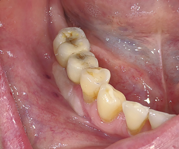
Intra-oral examination revealed a porcelain fused to metal (PFM) crown in relation to 45 (Figs. 1,2) along with an edentulous area in 46,47,48 region. The alveolar ridge in 46,47 region appeared normal, with a shallow vestibule and no keratinized gingiva. Previously placed crown in 45 region showed no occlusal contact to the opposing maxillary teeth. Panoramic radiograph (Fig. 3) revealed implants and supporting restorations in relation to 35,36 and 45 with a fractured implant body was noted in 46 region. CT of 45 and 46 (cross-sectional view) revealed adequate space of approximately 5×8.5mm and 5×7.3mm dimensions. (Figs. 4 & 5) The implants in relation to 45 and 46 were at a distance of 3.1mm and 3.5mm from the inferior alveolar canal correspondingly.
Fig. 1

Fig. 2
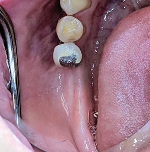
Fig. 3

Fig. 4

Fig. 5

Treatment plan:
- Removal of the crown in 45 and implants in 45,46 region
- Placement of wider diameter implants in 45,46 region (The patient had declined vertical ridge augmentation procedure as she did not want to undergo any invasive technique and could not wait for additional 9 months for treatment completion)
- Correction of thin gingival biotype to thick biotype using acellular dermal matrix (patient declined a CTG–as she did not want to undergo 2 surgeries on the same day–she did not like the idea of implant surgery and connective tissue harvesting from the palate the same day of surgery)
- Correction of inadequate keratinized gingiva with a free gingival graft
- Restoration with a screw retained splinted porcelain fused to metal restoration
Surgical procedure:
After pre-surgical preparation (patient was advised to brush her teeth, scrap her tongue thoroughly and rinse for 30 seconds with a cup of 0.12% chlorhexidine gluconate), local anaesthesia with 2% lidocaine and 1:100,000 epinephrine was administered as inferior alveolar nerve block, lingual and long buccal nerve block with two carpules. Rubber dam was placed in 45 region (Figs. 6,7 & 8) while sectioning of the PFM crown in order to prevent accidental aspiration or ingestion of the sectioned crown and to prevent splatter of ceramic or metal particles in the mouth prior to surgery.
Fig. 6
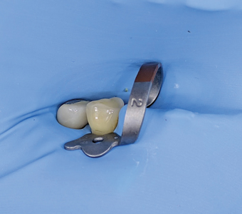
Fig. 7

Fig. 8
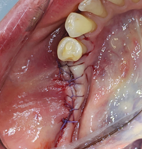
A crestal incision was given and full thickness flap was raised in 45, 46 region with a 15 no. BP blade. (Fig. 9) The fractured implant in 46 and single implant in 45 was then removed utilizing trephines. (Fig. 10) A surgical stent (an in-house fabricated essix type appliance made from the duplicate stone model of the lab fabricated anatomic wax up) was used to assist reorient the osteotomy in an ideal prosthetic position (Figs. 11 & 12) utilizing the Lindheman surgical bur (side cutting bur). (Fig. 13) Implants of 4.5 x 8.5mm dimensions were then placed in 45, 46 region respectively and primary stability achieved. (Fig. 14) The technique to help convert thin gingival biotype to thick biotype was performed by placing acellular dermal matrix (ACDM) over the implants. A tissue punch (Fig. 15) of 4.0mm diameter (Fig. 16) was used to create holes (Fig. 17) on the acellular dermal matrix and secured to the implants using the Poncho technique (Fig. 18) with 5.0 diameter / height healing abutments. Primary closure was achieved with 5-0 Vicryl sutures and hemostasis obtained. (Fig 19)
Fig. 9

Fig. 10

Fig. 11

Fig. 12

Fig. 13

Fig. 14

Fig. 15
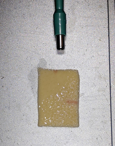
Fig. 16

Fig. 17
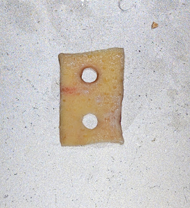
Fig. 18

Fig. 19
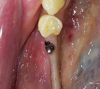
The patient returned 2 weeks later for postoperative evaluation and wound healing was found to be satisfactory. Two months after initial placement of implants, (Figs. 20 & 21) a second stage surgery was performed under local anaesthesia and taller healing abutments (5.0-6.0 diameter and 7.0 height) were placed (observe thicker tissue biotype in the region). (Figs. 22 & 23) A radiograph was taken to confirm the full seating of these healing abutments. (Fig. 24)
Fig. 20

Fig. 21

Fig. 22

Fig. 23
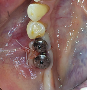
Fig. 24

Allowing another period of 2 months for healing, (Figs. 25 & 26) a free gingival graft surgery was performed to increase the amount and width of keratinized gingiva. During the procedure, a horizontal partial thickness incision (Fig. 27) was made at the junction of attached and free gingiva in the region of previously placed implants and vestibular deepening was achieved by performing supraperiosteal dissection. Following which a free gingival graft was harvested from the palate. (Figs. 28 & 29) Incision was given 2mm apical to gingival margin and dimension of the graft was determined using a template according to the defect at the recipient site. The harvested graft (Fig. 32) was then sutured to recipient site with chromic-gut sutures (Figs. 33 & 34) and donor site was managed with absorbable hemostatic gelatine sponges and an overlying acrylic palatal plate. (Figs. 30 & 31) The patient was followed up periodically and the wound healing was found to be uneventful at the donor and recipient site. (Figs. 35 & 36)
Fig. 25

Fig. 26
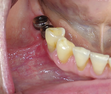
Fig. 27

Fig. 28
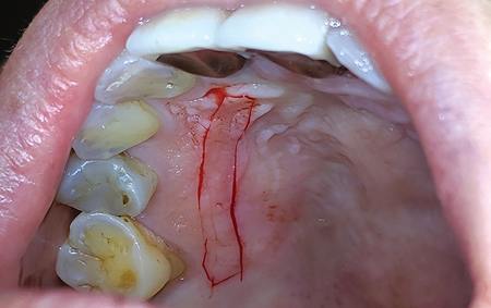
Fig. 29
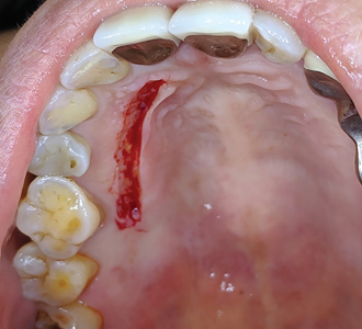
Fig. 30

Fig. 31

Fig. 32
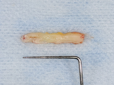
Fig. 33

Fig. 34
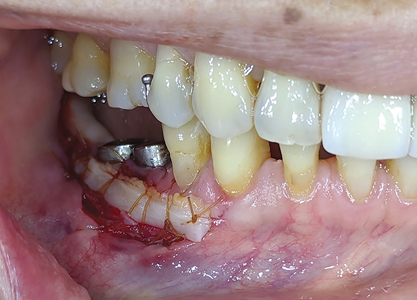
Fig. 35

Fig. 36

After a period of 3 months, the patient reported for final impressions (Figs. 37 & 38) with well healed tissues presenting adequate keratinized attached gingiva and vestibular depth. Open tray impression copings were placed (Fig. 39) and radiographs (Fig. 40) were taken to ensure the seating of the coping. PVS impressions (heavy and light body) were made with using an open transfer coping technique. (Fig 41) Bite registrations were recorded, opposing impressions made. (Figs. 42 & 43) In the following visit, a metal try-in (Figs. 44 & 45) was done to verify passive fit of the framework with radiographic confirmation (Fig. 46) of the fully seated metal framework. Using a Vita 3D Master guide, shade matching was done. (Fig. 47) On the final appointment, the restoration from the lab was disinfected with 0.12% chlorhexidine prior to placement in the mouth. The seating of the restoration (Figs. 48 & 49) was done and hand tightened.
Fig. 37

Fig. 38
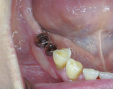
Fig. 39

Fig. 40

Fig. 41
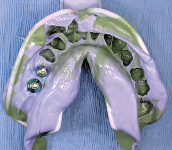
Fig. 42
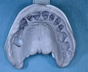
Fig. 43

Fig. 44
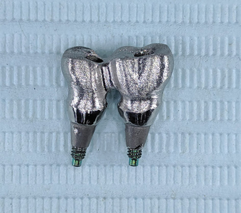
Fig. 45
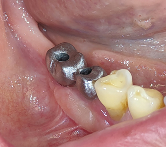
Fig. 46

Fig. 47

Fig. 48

Fig. 49

X-rays were taken to verify the seating of the components. (Fig. 50) Occlusion and proximal contacts were verified and adjusted as needed. The restoration was torqued with a calibrated torque wrench at 30Ncm and the screw access holes were sealed with teflon tape and flowable composite. Custom composite stains were used to mimic occlusal grooves. (Figs. 51 & 52)
Fig. 50

Fig. 51

Fig. 52
The patient was happy and satisfied with the aesthetics and feel of the new implants. (Fig. 53)
Fig. 53

DISCUSSION
The most common implant-related complications are biomechanical problems that occur after the implant is loaded. A literature review focusing on implant failure indicated these problems primarily occur within 18 months of initial implant loading. The most common complications that do not lead to the failure of the implant are also biomechanical problems. In implant-supported fixed prostheses, abutment or prosthetic screw loosening (7% to 10%), porcelain fracture (7%), and prosthesis metal fracture (3%) are examples of common complications. In addition, implant components (2% to 4%) and even implant bodies may fracture (1% to 2%)1.
The implant treatment plan to minimize biomechanical complications are modified primarily in two ways when implants are inserted in the posterior region2:
(1) additional implants that are wider in diameter are one method used to reduce the overload risk or (2) the elimination of posterior lateral occlusal contacts during excursive movements is recommended when opposing natural teeth or an implant or tooth supported.
The case in discussion for the 45,46 region was originally restored utilizing single piece narrow diameter implants. The initial treatment plan for implant dentistry should have included the ideal implant size, based primarily on biomechanical and esthetic considerations. The implant size directly affects the functional surface area that distributes a load transferred through the prosthesis. A comprehensive approach to the overall dental implant size begins with the identification of clinical problems to be addressed. Fundamental scientific principles related to force and surface area are then combined with engineering principles to pursue the desired clinical goals. A better way to understand biomechanics is to review the literature introduced by Carl Misch–Stress Treatment Theorem–Sequence of Treatment Planning3
- The final result (the prosthesis) should be visualized prior to the selection of the implant foundation.
- Because stress equals force divided by the area to which the forces are applied, the amount of force is directly related to the amount of stress. There are several force factors to consider, including: (1) bruxism, (2) clenching, (3) tongue thrust, (4) crown height, (5) masticatory dynamics, and (6) the opposing arch. The forces applied to the restoration also differ by their (1) magnitude, (2) duration, (3) type, and (4) predisposing factors (e.g., cantilevers)
- The density of bone is directly related to the strength of the bone. Misch et al. have reported on the biomechanical properties of four different densities of bone in the jaws. Dense cortical bone is 10 times stronger than the soft, fine trabecular bone. D2 bone is approximately 50% stronger than D3 bone.
- The surface area of each implant is directly related to the width of the implant. Wider root form implants have a greater area of bone contact than narrow implants (of similar design), resulting from their increased circumferential bone contact areas. Each 0.25mm increase in implant diameter may increase the overall surface area approximately 5% to 10% in a cylinder implant body. Bone augmentation in width may be indicated to increase implant diameter by 1 mm when force factors are greater than ideal. In addition, it has been suggested that an increase in implant diameter may be more effective to reduce stress.
- Implant macrodesign may affect surface area even more than an increase in width. A threaded implant with 10 threads for 10 mm has more surface area than one with five threads. A thread depth of 0.2 mm has less surface area than an implant with 0.4 mm.
- Once the previous steps to the treatment plan sequence have been determined, the available bone in the potential implant sites is evaluated. If available bone is not present, bone augmentation or modification is required.
Another area of discussion for this case was the importance of thicker tissue biotypes and keratinized mucosa around the dental implants. The most ideal way to convert a thin tissue to a thick biotype is through subepithelial connective tissue grafting, alternatives include the use of acellular dermal matrices4. In this case discussion–we opted to optimize the soft tissue by use an acellular dermal matrix during the implant surgery and supplement the soft tissue augmentation with a free gingival graft. The deficiency of keratinized and attached mucosa around the peri-implant site results in incompetent oral hygiene, plaque build-up, mucosal inflammation and alveolar bone loss that creates a negative impact of dental prostheses5. Hence, to avoid these biological complications, developing adequate keratinized gingiva improves the long-term prognosis of implant-supported restorations. A thick biotype comprising of large amount of attached keratinized gingiva provides greater resistance to traumatic or inflammatory recession. Warrer et al6 found the absence of attached gingiva increases the susceptibility of the implant site to inflammation and bone loss. In a human study, Bouri et al7 examined the significance of attached gingiva in subjects with dental implants. The team found higher plaque index scores around implants with a narrow zone of attached gingiva (< 2 mm) compared to implants with a wide zone (>2mm). Subjects reported an inability to brush these areas due to mucosal mobility and tenderness. The implants with a narrow zone of attached gingiva had a higher incidence of bleeding on probing and exhibited more significant bone loss. Chung et al8 reported that lack of attached gingiva was associated with higher plaque and gingival indices, especially on implants placed in posterior sextants.
The term periodontal biotype introduced by Seibert and Lindhe9 categorized the gingiva into “thick-flat” and “thin-scalloped” biotypes. Thick gingival tissue is associated with a broad zone of the keratinized tissue and flat gingival contour suggestive of thick bony architecture and also is more resistant to inflammation and trauma. Thin gingival tissue is associated with a thin band of the keratinized tissue, scalloped gingival contour suggestive of thin bony architecture and is more sensitive to inflammation and trauma. Thin gingival biotypes are delicate, highly scalloped and translucent in appearance. The soft tissue appears delicate and friable with a minimal amount of the attached gingiva. Patients with thin scalloped biotypes are considered at risk as they have been associated with a compromised soft tissue response following surgical and or restorative treatment.
Insufficiently keratinized tissue can be increased surgically by free gingival grafting. The presence or reconstruction of keratinized mucosa around the implant can facilitate restorative procedure and allow the maintenance of an oral hygiene routine without irritation or discomfort to the patient10.
CONCLUSION
Dental implants are highly successful treatment options for the replacement of missing teeth. Strategic evaluation and meticulous treatment planning can assist the clinician to execute the surgical and prosthetic phase with ease. Understanding the fundamentals of the biology and biomechanics for implant restorations in the posterior mandible along with the importance of soft tissue augmentation procedures can help improve the overall success of the implant restorations . This case report highlights the proper management of the treatment planning and execution for 2 previous implant restorations that were clinical failures and did not serve its intended purpose. The patient has been followed up for 3 years and the restorations have been successfully serving the patient in form, function and esthetics.
Oral Health welcomes this original article.
References
- Goodacre CJ, Bernal G, Rungcharassaeng K et al: Clinical complications in fixed prosthodontics, J Prosthet Dent 90:31-41, 2003
- Misch C. Treatment planning: Force factors related to the patient conditions. Chapter 6, Contemporary Implant Dentistry 3rd Ed, Mosby
- Carl E.Misch. Stress Treatment Theorem for Implant Dentistry. Chapter 4, Contemporary Implant Dentistry, 3rd Edition, Mosby
- H. Tal, O. Moses, R. Zohar, et al. Root coverage of advanced gingival recession: A comparatative study between acellular dermal matrix allograft and subepithelial connective tissue grafts J Periodontol, 73 (12) (2002), pp. 1405-1411
- Souza AB, Tormena M, Matarazzo F, Araujo MG. The influence of peri-implant keratinized mucosa on brushing discomfort and peri-implant tissue health. Clin Oral Impls Res. 2016;27:650–655.
- Warrer K, Buser D, Lang NP, Karring T. Plaque-induced peri-implantitis in the presence or absence of keratinized mucosa. An experimental study in monkeys. Clin Oral Implants Res. 1995;6:131–138.
- Bouri A Jr, Bissada N, Al-Zahrani MS, Faddoul F, Nouneh I. Width of keratinized gingiva and the health status of the supporting tissues around dental implants. Int J Oral Maxillofac Implants. 2008;23:323–326.
- Chung DM, Oh TJ, Shotwell JL, Misch CE, Wang HL. Significance of keratinized mucosa in maintenance of dental implants with different surfaces. J Periodontol. 2006;77:1410–1420.
- N. Claffey, D. ShanleyRelationship of gingival thickness and bleeding to loss of probing attachment in shallow sites following non surgical periodontal therapy. J Clin Periodontol, 13 (1986)
- Wennström J. L., Derks J. Is there a need for keratinized mucosa around implants to maintain health and tissue stability? Clinical Oral Implants Research. 2012;23(supplement 6):136–146.
About the Author
 Dr. Joshua Shieh is a Fellow of the International Congress of Oral Implantology and of the Acad. of General Dentistry, member of the American Acad. of Cosmetic Dentistry, Clin. Instructor at the Oral Rehabilitation Unit, Dept of Periodontics, Faculty of Dentistry at University of Toronto. He currently practises as a general dentist in Mississauga, Ont. drjoshuashieh@gmail.com
RELATED ARTICLE: An Alternative Prosthetic Design for Lower Full-Arch Implant Restorations