The loss of a tooth can be a stressful event for any individual. Upon learning that a tooth in the esthetic zone has been lost, or is going to be extracted, a patient’s immediate statement is almost always: “I don’t want to lose a tooth!” followed by the question: If that’s going to happen, how do we put it back?” The expectation is that the same esthetic presentation of the tooth prior to loss should be achieved by the treating dentist on delivery of the replacement restoration. While that is a fairly simple request for a patient to make, achieving that type of result can require careful and meticulous treatment.
Communication of tissue positioning to the dental laboratory is of critical importance to the successful completion of any restorative case. While registration of static tissues (tooth and bone) is easily captured with either physical or digital impression methods, movable gingival tissues provide a different challenge. As gingival tissues move and maintain equilibrium under the pressure of teeth and restorations that contact the tissues, recording planned post-restorative gingival position can be difficult. In order to eliminate guesswork for the restorative team modified impression protocols may be employed. This is the exact challenge encountered in the restoration of a missing tooth with a dental implant.
DIAGNOSIS
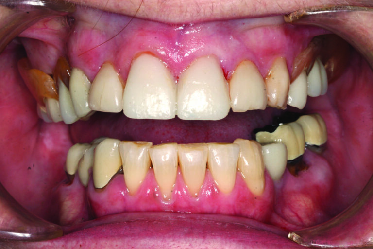
A 77-year-old female in good medical and dental health presented for restorative consultation stating she maintains annual dental cleanings. She stated that she wanted to improve her smile and was interested in eventually finding a fixed restorative replacement for her existing maxillary removable partial denture. The patient stated that she was concerned about some degree of mobility in her upper right permanent incisor (tooth #8). Radiographic examination was performed including a full mouth series of periapical radiographs and a panoramic radiograph. Some generalized bone loss was noted along with severe vertical bone loss around tooth #8. Clinical examination revealed a Class I dental relationship with no significant occlusal interferences.1 Numerous fixed restorations were observed along with the presence of an upper flexible removable partial denture. Several areas of gingival asymmetry were also noted.2 Evidence of generalized significant wear was found throughout the patient’s dentition along with abfractions and some super-eruption of posterior teeth, however, the patient exhibited no symptoms of any temporomandibular disorder and appeared asymptomatic during a T.M.J. evaluation. (Fig. 1)
Fig. 1

The patient was then referred to a periodontist for a consultation regarding her overall periodontal health and a focus on treatment of tooth #8.
TREATMENT PLAN
After an interdisciplinary case conference between the periodontist and the restorative dentist, the patient was asked to return for a planning appointment.2 The patient expressed a desire to begin pursuit of comprehensive restoration of her dentition but, due to financial concerns, she was only comfortable completing treatment in segments. As tooth #8 exhibited significant bone loss secondary to a vertical root fracture and was a risk for further infection, removal of the tooth was determined to be the starting point for her treatment. While several different methods for restoration of her missing tooth were discussed, the patient selected placement of an endosseous implant to serve as the definitive restoration. Alternative considerations included a 3-unit fixed bridge or a removable prosthesis. As the patient desired to have #9 restored with a new crown to mirror the shape and color of her new implant crown, and to postpone additional treatment of her other anterior teeth until a later date, an endosseous implant was determined to be the best choice to restore the failed tooth #8. The patient emphasized that a natural, conservative, long-lasting result was her primary goal. Proper care for the future restorations was discussed including nightly wear of a hard protective occlusal guard, and the importance of optimal maintenance including regular cleanings and examinations was stressed.1
DESCRIPTION OF TREATMENT
Due to the severity of the osseous defect around tooth #8 the periodontist elected to perform implant placement as a two-step procedure. The restorative dentist first prepared teeth #8 and 9 for full coverage crowns. (Fig. 2) The periodontist removed the failed incisor tooth #8 and placed a particulate bone graft in the defect. A provisional cantilever bridge with a pontic replacing tooth #8 supported by tooth #9 as an abutment was placed. The apical extent of the tooth #8 pontic was designed to be polished smooth to allow for healing and to maintain tissue support.
Fig. 2
Following a four-month healing per-iod, the periodontist removed the provisional bridge and placed an endosseous implant in the #8 area. The implant (Straumann; Andover, MA) was placed at the apical extent of the tissue developed by the pontic and covered so the pontic would not pressure the implant during the healing phase. Following an additional four-month healing period, osseointegration of the tooth #8 endosseous implant was confirmed, and the patient was released to the restorative dentist.
At the first appointment following release from the periodontist the provisional bridge was removed and the soft tissue contours were evaluated. A new provisional crown was fabricated for tooth #9 and a screw retained implant crown for tooth #8 was fabricated on a stock provisional abutment to further develop tissue support and emergence profile. A photograph was made to document the location of the access hole on the screw retained crown to simplify location of the access hole at the next appointment. (Fig. 3) A piece of Teflon tape was placed in the access hole to protect the screw head and the access hole was filled with flowable composite and cured. (Figs. 4 & 5) The access cover was then shaped and polished to be imperceptible from the facial presentation of the crown. (Fig. 6) The new set of provisionals were left in place for a minimum of two weeks to allow for tissue adaptation and remodeling.
Fig. 3

Fig. 4

Fig. 5

Fig. 6

After a minimum time period of the tissue support remaining stable with an acceptable presentation, a final records appointment was scheduled with the restorative dentist.
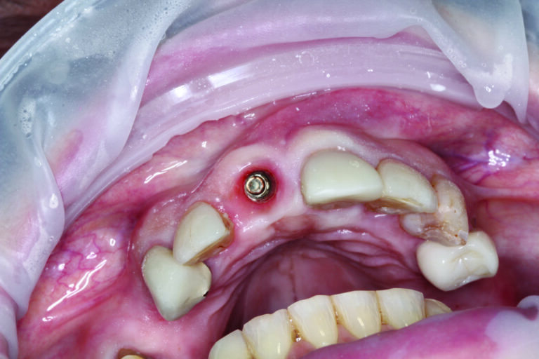
At presentation for the final records appointment the patient was first scanned for a digital record of her approved provisionals. (Fig. 7) Photographs documenting presentation, contour, shape, and shade were made.3 (Figs. 8 & 9) The area surrounding teeth #8 and #9 was anesthetized and adequate retraction of the lips was achieved utilizing an Optragate retractor (Ivoclar Vivadent; Amherst, NY). The access hole for the screw retained provisional implant crown on tooth #8 was located and opened. The Teflon tape was removed, and a hand driver ligated with dental floss was used to loosen and remove the provisional implant crown. The provisional crown on tooth #9 was also removed. At this point the restorative platform of the implant was visible as well as the soft tissue interface previously supported by the contours of the provisional implant crown. (Fig. 10) The second the provisional implant crown was removed, soft tissue contours started changing as they no longer experienced support from the provisional. For this reason, it was important to be able to communicate the emergence contour of the provisional implant crown to the laboratory to facilitate exact replication of the tissue support.
Fig. 7

Fig. 8
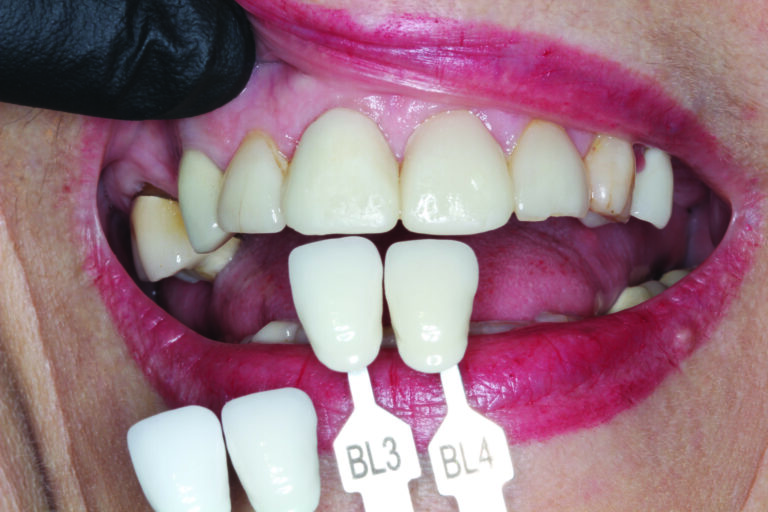
Fig. 9
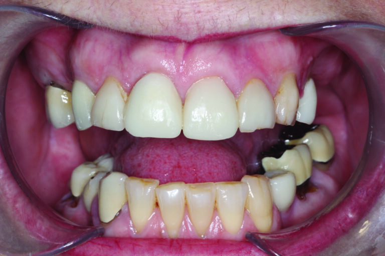
Fig. 10
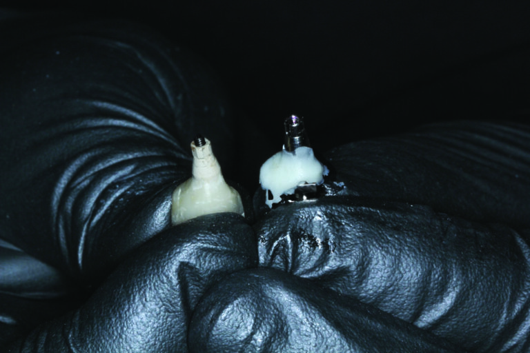
On the bench, the approved provisional implant crown was seated into a corresponding lab analog and screwed down. (Fig. 11) The lab analog and provisional implant crown were covered up to the height of the crown contour with clear bite registration material (Den-Mat; Lompoc, CA) and seated in a dappen dish for the bite registration to cure. (Fig. 12) The facial and lingual orientations were marked on the impression prior to removal of the crown from the set impression material. (Fig. 13) Once the clear bite registration material had hardened, the provisional crown was unscrewed and removed from the impression. The appropriate size open tray impression coping was then seated into the lab analog secured in the bite registration material and screwed down for a positive seat. Flowable composite (Kuraray America; New York, NY) was then injected into the impression space between the bite registration material and the pickup coping. (Fig. 14) It was important to keep the tip of the composite cannula submerged in the composite during injection to prevent air bubbles. Once the area up to the height of contour of the crown was filled, the composite was stacked up the sides of the impression coping to engage in the lowest anti-rotational grooves. The composite was then cured fully for one minute from all angles through the clear bite registration. (Fig. 15) Once the material was completely cured the impression coping was unscrewed and removed from the dappen dish registration material.(Fig. 16) Side by side comparison of the modified impression coping and the provisional implant crown demonstrated an exact replica of the tissue support. (Fig. 17)
Fig. 11
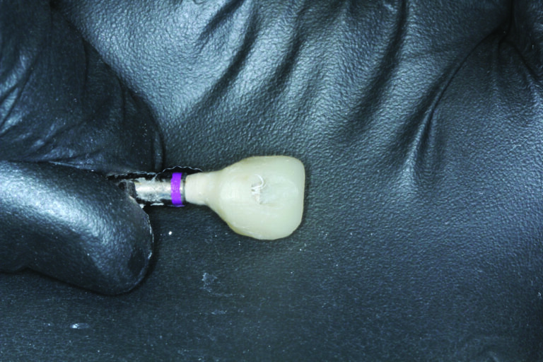
Fig. 12
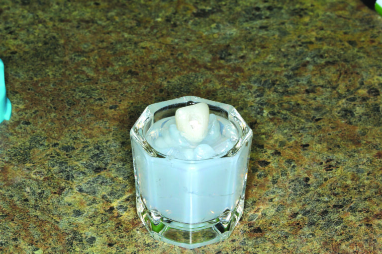
Fig. 13
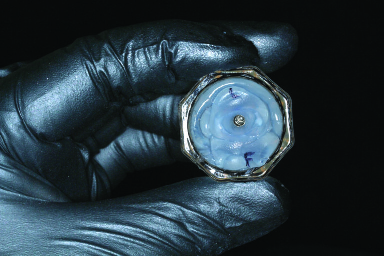
Fig. 14
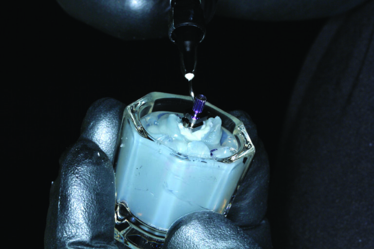
Fig. 15

Fig. 16
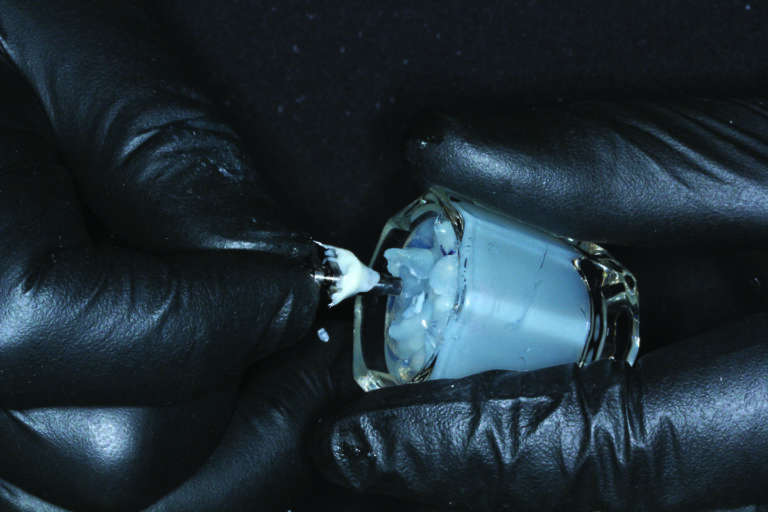
Fig. 17
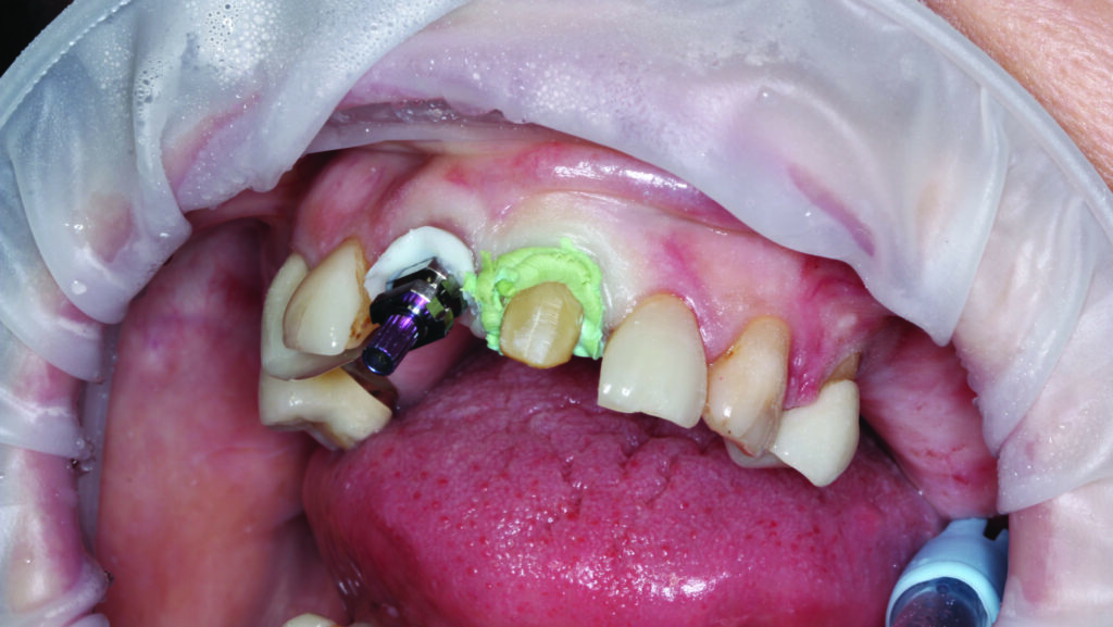
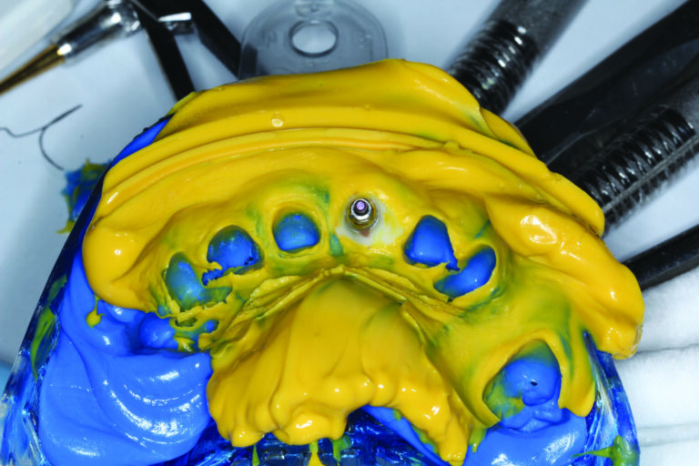
The modified impression coping was then placed in the patient’s mouth and screwed down into the tooth #8 implant making sure to mind and match the orientations recorded on the dappen dish. At this point, several areas of tissue blanching could be noted signifying the movement of tissue contours that had “relaxed” during the short time the tissue was unsupported by the provisional crown. (Figs. 18 & 19) A positive seat of the impression coping was confirmed radiographically. Expa-syl gingival retraction paste (Acteon Group; Mèrignac, France) was expressed around the gingival margin of tooth #9 to provide hemostasis and adequate tissue reflection. (Fig. 20) After 3 minutes the paste was rinsed away with a copious, forceful water spray. The preparation and impression coping were dried, and a master polyvinyl impression was made with Honigum Pro Light and Heavy impression material (DMG America; Ridgefield Park, NJ). Following set of the polyvinyl material, the modified impression coping was unscrewed and removed as part of the master impression. (Figs. 21 & 22) The screw retained tooth #8 implant provisional was replaced and the provisional tooth #9 crown was, once again, bonded into position. Teflon tape was again placed into the access hole of the implant provisional, and matching flowable was used to cover the access until the future case delivery date. Upon inspection of the intaglio of the open tray implant impression, a precise replication of the emergence contours and tissue margin for the tooth #8 implant can be visualized. (Fig. 23)
Fig. 18
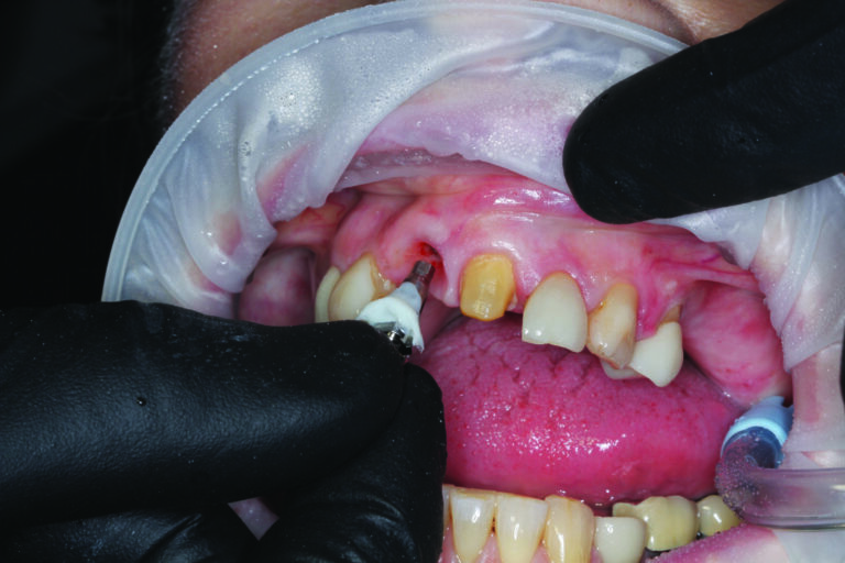
Fig. 19
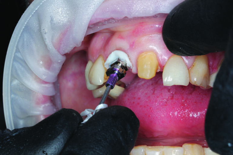
Fig. 20

Fig. 21
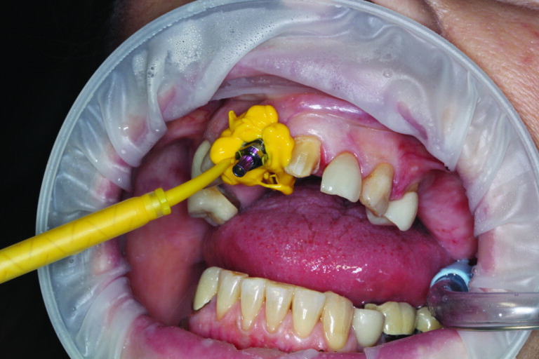
Fig. 22

Fig. 23
A missing permanent incisor presents a complex esthetic and restorative problem. Meticulous attention to both function and esthetics are essential to achieving restorative success. Management of soft tissue is of paramount importance. With careful planning and precise execution, excellent records can be provided to the laboratory specialist to aid in the development of an exceptional restoration. 
Oral Health welcomes this original article.
References
- Dawson, Peter E. Evaluation, Diagnosis, and Treatment of Occlusal Problems. The C.V. Mosby Co.: St Louis, MO; 1989.
- American Academy of Cosmetic Dentistry. Diagnosis and Treatment Evaluation in Cosmetic Dentistry: A Guide to Accreditation Criteria. Madison (WI): The Academy; 2001.
- Fradeani, Mauro. Esthetic Analysis A Systematic Approach to Prosthetic Treatment Volume 1. Quintessence Books: Chicago, IL; 2004.
About the Author:

Dr. Johnston Rowe, Jr. maintains a private practice in Jonesboro, Arkansas. He is an Accredited Member of the American Academy of Cosmetic Dentistry, past member and Chairman of the American Board of Cosmetic Dentistry, and has served as the AACD’s Chairman of Accreditation. He also serves as an Accreditation Examiner for the American Academy of Cosmetic Dentistry. Dr. Rowe has been awarded Fellowships in the International College of Dentists and the Pierre Fauchard Academy. He enjoys sharing his passion for cosmetic dentistry materials and techniques, lecturing nationally and internationally, and can be contacted through his office at info@rowesmiles.com or 870.932.4126.