As it has been stated by Dr. Harold M. Shavell, “Occlusion and morphology are the common denominators of all dentistry.”1 A single tooth or restoration can profoundly affect a patient’s function and comfort if it is not properly integrated into the patient’s natural occlusal function. It is unfortunate that “modern” dentistry has such a “conformative” approach under the guise of being “conservative” or committing “over-treatment”. With the “tooth-at-a-time” or “if it’s not broken, don’t fix it” approach, are we really doing our best to help patients keep their teeth for the rest of their lives? How many teeth, as Dr. Shavell would say, “have been sacrificed on the altar of false conservatism?” These are questions we all wrestle with every day in private practice. One thing that is important to remember, the muscles always win! Without proper integration into a non-interfering occlusal scheme, the best restorative effort will ultimately fail regardless of the material used. The following is a case report that illustrates these premises while addressing the replacement of a single tooth restorative failure. 2,3
A CLASS IV COMPOSITE FAILURE: CASE HISTORY AND RESTORATIVE PLAN
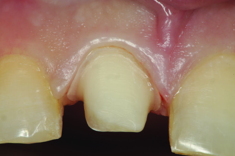
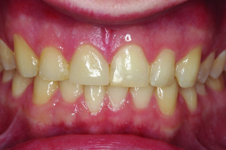
The patient in Figure 1 presented with a broken Class IV mesial incisal composite restoration on tooth #8. It had been replaced three times during the past year and has broken again. Aside from the amount of composite on the facial surface that extends beyond the area of the fractured area, a majority of the lingual (palatal) surface of the tooth is worn through to dentin due to hyperfunction in protrusive and lateral excursions for many years, creating a functional as well as aesthetic dilemma for this patient. A “conservative” approach may be simply to bond the tooth again with composite and hope for the best. However, this may not be the best long-term approach when considering the functional stress in this area even with the best tooth alignment. After all, how “conservative” is it to continually “assault” the tooth with rotary instrumentation to keep “fixing” a composite that continues to break? What about the alignment of the opposing teeth? It can be seen in Figure 2 that excessive incisal wear is present on the incisal edges of tooth numbers 24 and 25. From the incisal view (Fig. 3) extensive wear is seen on all mandibular anterior incisal edges because of occlusion (occlusal disease) that is often seen yet left untreated. Tooth number 25 is also facially positioned so that in protrusive excursions, it engages the palatal surface of tooth number 8, prematurely placing additional stress on both the palatal surface and incisal edge of tooth #8 before coupling with the remainder of the maxillary anterior segment. So, addressing these issues restoratively involves more than just fixing a chipped composite restoration. Orthodontics to correct tooth alignment was discussed with the patient, but there was no interest. A “Plan B” could be to restore tooth #25 in such a way that the position of the tooth facially and the incisal edge do not engage the palatal surface of tooth #8 prematurely, then restore the palatal surface and incisal facial fractured area with ceramic to replace the lost enamel and reinforce what remains. The decision was made to restore tooth #8 with a ceramic restoration and tooth #25 with a direct composite. Aesthetically, for tooth #8, an aesthetic match to tooth #9 could be better achieved in layered ceramic. Composite resin was chosen as a more conservative and less costly option for tooth #25, but the patient was told that it may require a ceramic restoration later.
Fig. 1

Fig. 2
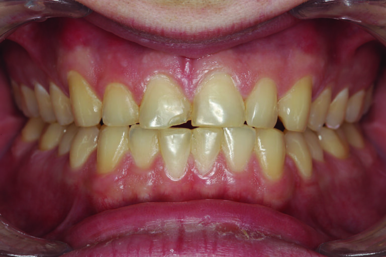
Fig. 3

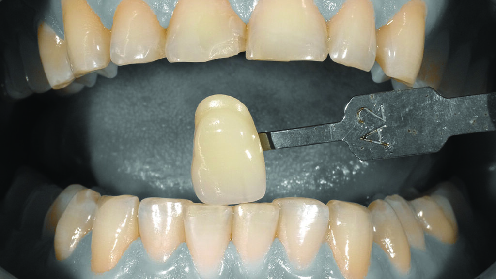
OPERATIVE PROCEDURE #1 – TOOTH #25 DIRECT COMPOSITE VENEER
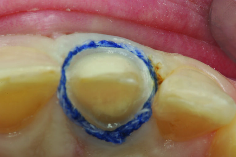
A preoperative shade was chosen and photographed (Fig. 4) for the ceramist using a digital camera with a function that isolates the tooth shade from the rest of the oral cavity (EyeSpecial C-2: Shofu). Next, the facial surface of tooth #25 is prepared “orthodontically” to move the facial surface and incisal edge lingually (Fig. 5). After preparation, it is important to note that the bevelled facial surface of tooth #25 has a knife-edge cervical margin of about 2 mm supragingival. This long bevel” will allow for a more aesthetic blend of composite and tooth structure while leaving the emergence profile of the natural tooth untouched. Figure 6 shows the positioning of a Uveneer Template (Ultradent Products), which will be used to fabricate the facial and incisal anatomy in composite and “move” the tooth (tip) in the lingual direction. Prior to placement of composite, the tooth (enamel) surface is etched with Phosphoric Etch (Ultra Etch: Ultradent Products) for 15 seconds, thoroughly rinsed, and then air dried. A universal bonding resin (Peak Universal: Ultradent Products) is applied to the tooth surface, air-thinned, evaporating the solvent, and then light cured for 20 seconds (Valo Grand: Ultradent Products). Figure 7 shows the initial increment of composite used to build up the incisal one-third of the tooth to its new “lingualized position.” The Uveneer template is then filled with the chosen shade of composite (Mosaic Universal Composite: Ultradent Products) and placed on the facial surface of the tooth in the proper alignment with the adjacent teeth and light cured. Figure 8 shows tooth #25 after removal of the Uveneer template and some minor incisal adjustments and polishing.
Fig. 4

Fig. 5
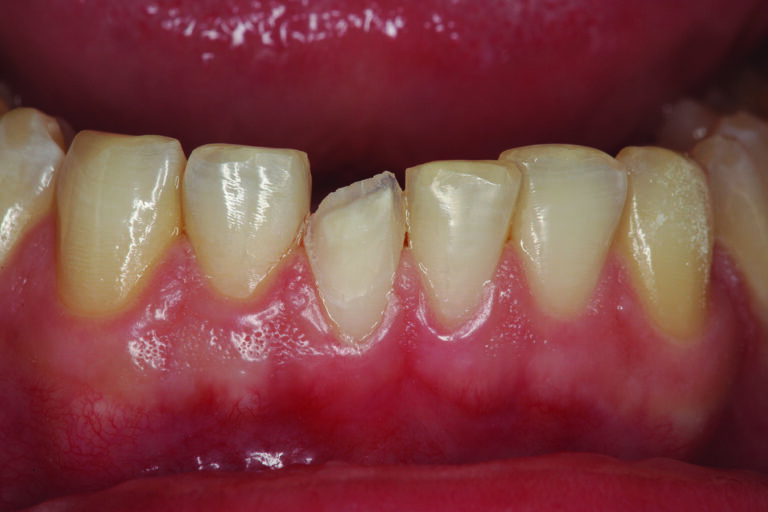
Fig. 6

Fig. 7

Fig. 8

OPERATIVE PROCEDURE #2 – TOOTH #8 ALL CERAMIC RESTORATION
Tooth #8 is prepared for an all-ceramic crown. It is important to stress the preparation of the palatal surface is critical. It must be prepared for 1.0-1.5 mm of reduction following the curvature of the unprepared palatal surface (maxillary palatal concavity). This is so the restoration can follow the natural palatal curvature at the appropriate thickness of restorative material for strength. Remember, the maxillary palatal concavity is determined by the angle of the eminence and the envelope of function, both occlusal determinants that must be followed when restoring maxillary anterior teeth (Figs. 9 and 10). Once the preparation is completed (Fig. 11), the master impression can be made.
Fig. 9
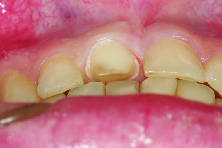
Fig. 10

Fig. 11
THE “TWO-CORD “ TECHNIQUE FOR INDIRECT IMPRESSION MAKING
A two-cord impression technique is an extremely predictable way to capture quality master impressions for full coverage (circum-coronal) and partial coverage restorations with either intra-crevicular or equi-crevicular margins (at the free gingival margin.)4 First, a #00 retraction cord (Ultrapak: Ultradent Products) is placed at the base of the gingival sulcus around each preparation, starting from the lingual aspect, around the proximal to the facial aspect, then back through the opposite proximal area to the lingual starting point. The excess at both lingual ends is trimmed, and the opposing ends of the cord are tucked into the lingual gingival sulcus so that they butt against one another (not overlapping!). Once the first retraction cord is properly placed and prior to placement of the second retraction cord, any minor marginal correction can be done to the preparation using a course or fine diamond instrument of the appropriate diameter. Next, a #1 cord (Ultrapak: Ultradent Products) is placed on top of the #00 in the same manner as previously described. If desired, all cords may be soaked in a hemostatic solution (Viscostat Clear: Ultradent Products), then excess removed with a 2X2 gauze sponge prior to placement. Next, using a cotton pledget, the preparation is wiped with Consepsis (Ultradent Products) to make sure the surface is clean and free of “prep debris” from the diamond instrument. When ready (usually after all cords are in place and the fit of the impression tray has been verified), the #1 cord is partially pulled out of the sulcus using an explorer on the facial aspect of each preparation and the amount of retraction (and lack of moisture or blood contamination) is evaluated. Remember, the master impression must capture not only the entire restorative margin but also 0.5 millimetres of the tooth/root surface apical to the margin. If the marginal gingiva adjacent to any restorative margin rebounds to contact the tooth/margin after the top cord is pulled, a small piece of a larger diameter cord (#2) (Ultrapak: Ultradent Products) is placed into the affected area for an additional minute and then removed. This added retraction should be sufficient to create a space between the tooth surface and the inner dimension of the gingival sulcus. The goal of retraction is to “create a moat (space in which to inject light-bodied impression material) around the castle (tooth preparation).”
A SUPER PULSED DIODE LASER AS AN ADJUNCT TO CORD PACKING
If any portion of the circumferential gingival tissue is not sufficiently retracted away from the emergence profile of the tooth/preparation after placement of the #1 retraction cord, a diode laser can be used to perform a minor gingivoplasty on the overlapping gingival tissue above the top cord so that it is visible prior to its removal. This is common in interproximal areas where the gingival tissues (papilla) may be “slightly enlarged.” It is not recommended to “hope” that the heavy-bodied tray material will “push” the tissue out of the way to let the light body can access the gingival crevice. Figures 12 and 13 show the super pulsed diode laser (Gemini: Ultradent Products) performing a gingivoplasty above the top cord, with the retraction cord entirely visible before removing and injecting the light body impression material. When the cord is removed, an impression of the margin and 0.5 millimetres of tooth/root surface apical to the margin is virtually assured. To capture a precise master impression, light-bodied impression material should be injected not only around the prepared teeth but also overall occlusal and incisal surfaces so that the stone models can be accurately articulated. After injection of the light-bodied material, the impression tray with the heavy-bodied impression material is placed in the mouth according to manufacturers’ recommendations.
Fig. 12

Fig. 13
DELIVERY OF THE ALL CERAMIC RESTORATION
Figure 14 shows a retracted smile view of the provisional restoration and gingival tissues around tooth #8 prior to delivery of the definitive restoration. After removal of the provisional restoration and removal of any remaining provisional cement, the restoration is tried in, proximal contacts and occlusion are adjusted then polished as necessary. Next, the preparation is disinfected with Consepsis (Ultradent Products). Also, the laboratory has etched the restoration, so the etched surface is treated with a silane coupler before cementation per the manufacturers’ instructions. The restoration is then luted using dual-cured resin cement (Permaflo DC Translucent: Ultradent Products). Figures 15 and 16 show the restoration of tooth #8 with an all-ceramic crown after cementation.
Fig. 14
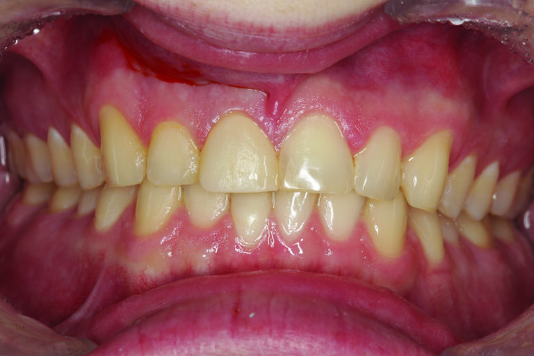
Fig. 15

Fig. 16

It is important to always consider that the restoration of a single tooth can affect the occlusion in a profound way. The reverse is also true not considering the occlusion can affect a single restoration both in contour and longevity. It is always recommended to consider these issues prior to any restorative endeavour.
 Fig. 17
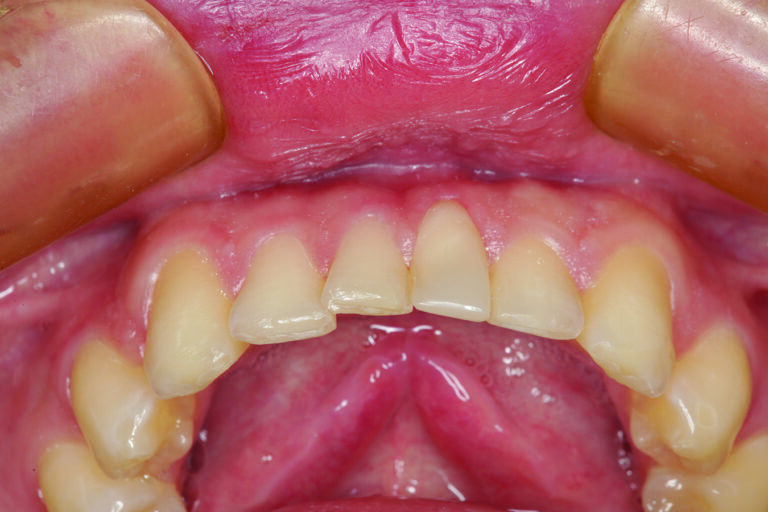
Fig. 18
Oral Health welcomes this original article.
References
- Shavell HM, Lost Art, Lost Discipline Part 1, JPDA Vol.22 No. 3, July-Sept 2013, pp. 164-177.
- Parker MW, The Significance of Occlusion in Restorative Dentistry, Dental Clinics of North America, 37(3) June 1993, pp.341-351.
- Neff P, Trauma from Occlusion Restorative Concerns, Dental Clinics of North America, 39(2), March 1995 pp. 335-354.
- Cloyd S, Puri S, Using the Double Cord Retraction Technique of Tissue Retraction for Making Crown Impressions, Dentistry Today, 18(1) January 1999, pp. 54-59.
About the Author:

Dr. Robert A. Lowe graduated magna cum laude from Loyola University School of Dentistry in 1982. He is an Assistant Professor in the Department of Oral Rehabilitation at MUSC James B Edwards College of Dental Medicine. He lectures internationally and publishes in well-known dental journals on esthetic and restorative dentistry. He is a clinical evaluator and a consultant for many prominent dental manufacturers. Dr. Lowe received the 2004 Gordon Christensen Outstanding Lecturers Award and the Diplomat status on the American Board Of Aesthetic Dentistry in 2005. He is a founding member of the World Clinical Laser Institute. Dr. Lowe can be reached for questions at 704-450-3321 or at boblowedds@aol.com