The loss of anatomy and architecture resulting from caries damage is the main cause of biomechanical transformations of the dental organ, leading to its weakening.1 Restoring the mechanical continuity and coronal-radicular seal of the tooth by restoration with fiber post and composite adhesives without aggravating this embrittlement is a priority objective, requiring the conservation of a maximum of residual tissues and the use of composite materials because of their better bonding and stress-reducing capacity.2
A multi-posts concept offers a less invasive anatomical root anchorage method combined with continuous reinforcement of the entire coronal-radicular restoration (Fig. 1a). This system consists of the insertion of many 300-micron (0.3-mm) diameter fiber-composite micro-posts distributed throughout the structure into the composite material used for the bonding and restoration.
Fig. 1AB

The solution presented in this article is based on a critical analysis of current concepts, our knowledge of the application of architectural composites to dental prostheses3 and the results of numerous tests and trials that carefully describe the device’s chemical, biological and mechanical characteristics.
Complex root canal morphology: If the visualization of the canal on a retro-alveolar radiograph of a premolar suggests a cylindric-conical canal, a cross-sectional view clearly shows that a single central post will only occupy a reduced part of the canal. (Fig. 1b) On the other hand, an anatomical coronal-radicular restoration of the inlay-core type will fill all the available spaces (Fig. 2).
Fig. 2

Analysis of the current concepts of coronal-radicular dental restoration.
The fitted post: The tooth canal is drilled with a homothetic drill bit to the selected prefabricated post in this concept. The post is made of a fibre-reinforced composite material and is bonded to the sides using a composite adhesive.
The coronal post is fabricated from a plastic-filled composite material, usually resin and particles. The coronal portion of the core is only partially reinforced during the restoration (Fig. 3).
Fig. 3

The first limitation relates to the anatomy of most dental canals.4
It appears that the fit of the machined post that should adapt to the entire endo-canal periphery is not feasible (Fig. 2). The anatomical conditions mean that intimate contact with the surfaces is not often obtained except by extensive canal drilling, thus weakening the root.
The concept of a floating post in the canal has been proposed,20 in which the fibre-based post floats within the canal space (Fig. 2). This concept seems to conflict with the principles of bonding: Bonding between two substrates is generally based on obtaining a large contact area between the substrates and the thinnest possible adhesive film. Generally, any gap will be filled with a large amount of bonding composite.
Polymerization stresses on both interfaces (dentin/adhesive and adhesive/strand) can cause delamination and infiltration, compromising the restoration in the medium term.10 In both cases, a central post does not reinforce the coronal restoration composite or the dentin. The “post should be an extension into a shaped canal, not an intrusion into the root dentin.”7
The second limitation is the limited flexibility of a standard machined post with a diameter greater than 300µ and its structural difficulty in following the path of a dental canal, which can often present a curvature.
Anatomical posts: They reproduce the anatomy of the root canal without the endodontic filling materials. The post adapts to each root canal morphology, preserving the integrity of the root dentin. These fibrous posts, which adapt to the canal shape, display better mechanical properties.5
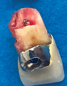
Metal core inlays: An inlay core becomes unavoidable when the tooth has lost its natural strength. It may be constructed of highly rigid metal, which can cause irreparable fractures (Fig. 4).10
Fig. 4
Techno-composite inlay cores: An alternative to traditional metal inlays is the indirect fabrication of inlays machined in CAD CAM technology in fibro-architecture discs or blocks. These composites are continuous fibres or woven strands impregnated with particle-embedded resin. They are designed to resist multidirectional functional stresses, and their rigidity lessens these stresses, mimicking the function of dentin (Figs. 4abc).
Fig. 4ABC

The woven strands are oriented in directions adapted to the direction and intensity of the stresses in each reconstruction area in fine element modelling studies.22
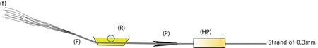
Multi-posts: The concept of multi-posts aims to respond to the observations of the critical analysis of traditional fibered composite solutions. Ultra-thin composite strands with a diameter of 300 microns constitute the multi-posts, which fit into the available canal space after the simple removal of the filling material, without the need for drilling to a predefined shape, which can have a de-forming effect.
They are produced by a robotic pultrusion process with continuous monitoring and self-adapting control (Fig. 5).
- 820 continuous elementary filaments of 9 µm diameter of textilo-plastic silanized E-glass (f)
- Constitute a twisted rod (F)
- They are impregnated with Yfb3 micro-filled Urethane Di Methacrylate (UDMA) resin (R)
- Pultruded in a fibre (P) of 300 µm diameter without releasing agent and highly polymerized (HP)
Fig. 5
Each element in the manufacturing process produces a feature:
| Manufacturing Process | Results Obtained |
| Filaments: | |
| E Glass filaments | Light conductive |
| 9 µm diameter filaments | High tensile strength |
| Textile-plastic silanization | High bonding to resin. |
| Reliable bonding to UDMA resin. | |
| UDMA resin: | |
| Yfb3 particles | Biocompatible Radio-opacity No Epoxy, No BisGMA |
| Pultrusion: | |
| Pultrusion without greasing agents | Ready to use Silanization not needed |
| High-temperature polymerization | |
| Post-curing | Stability: Low water absorption |
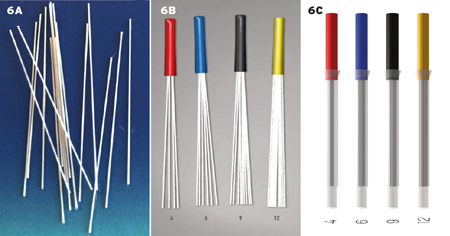
The small section strands (300 µm) are calibrated to their useful length (Fig. 6a) and assembled in a sheath grip for easy handling (Fig. 6b). They are available in an impregnating case designed to secure their impregnation without voids or bubbles with the filling resin. (Fig. 6c)
Fig. 6ABC
Why use micro-posts?
Multi-posts permit the reconstruction to adapt to the functionality of the tooth and not the tooth to the reconstruction.21
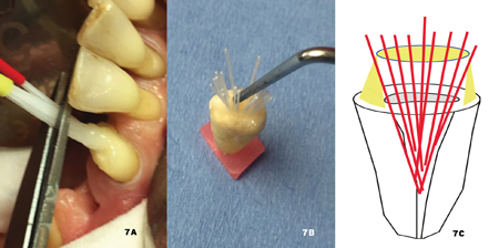
After the sheath is cut by scissors (Fig. 7a), the individual micro-posts are freely distributed in the available space to create a continuous fibro-architectural network from the root to the crown. Their organization can be aided with a simple probe prior to polymerization of the adhesive composite, and they can be effectively distributed throughout the entire reconstruction. (Figs. 7abc)
Fig. 7ABC
Overview of fibre composite materials: Composite materials are heterogeneous materials, formed of at least two elements in various phases: essentially, posts are continuous fibres and composite resins containing particles, binding the fibres together.
The components gather in a geometric structure that gives the final material superior properties to those of the individual components. It is a configuration that judiciously combines the properties of the fibres, particles and resins, allowing them to fulfill their technical function.8
It has been shown that the position and distribution of the fibres in the resin strongly influence the fracture resistance of the fibre material: it is more effective if the fibres are in areas of high stress.9
For coronal-radicular restoration, these areas are located at the periphery of the coronal stump.22 Therefore, fibre reinforcements should ideally be in the peripheral areas of higher stress.
The “crack stopper” role of fibres
Composites do not lack strength or hardness, but they do lack toughness: (Toughness is the ability of a material to resist crack propagation.23 The fracture toughness of a composite is between 0.6-2.0 MPa m0.5, a ceramic hybrid which is, in fact, a composite is at 1.5 (VITA data), which classifies them as brittle materials.
The degradation process of a coronal root canal restoration with a central fibrous post is the consequence of this lack of toughness in composites: Upon impact on a low-tenacity composite forming the core of a traditional central root post, micro-cracks form in the material at the point of impact, which inevitably widen in depth.
Subsequently, the marginal disintegration of the composite occurs, followed by the mobility of the peripheral, cap, and finally, the fracture of the fibrous ring and loss of the prosthesis. (Figs. 8abc)
Fig. 8ABC

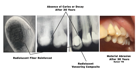
More than 30 years of experience with fibro-architecture infrastructures systematically indicates that they limit the delamination of composites by a crack-blocking effect (Fig. 9).23
Fig. 9
A “bouquet” organization of the micro-posts in the root canal space will reinforce the largest possible composite volume.
Preliminary studies
The viscoelastic properties of fibre-reinforced composites are clinically demonstrated by a lower number of root fractures than metal posts (Fig. 4).11,12 In a study,13 it was shown that the location of the fracture, when it occurs, changes according to the nature and/or organization of the reinforcement. It is more apical with rigid materials, a high Young’s modulus (metal), and increasingly coronal with materials close to dentin (18.5 GPa), increasing the chance of repair.
High-stress areas are always located in the periphery, at the neck of the coronal stump.
Mathematical modelling using finite element software (Abacus Dassault System) compared the behaviour of dentin under load at 30° of a restoration consisting of a fibrous central post (Master post) containing a coronal part of the particle composite (Fig. 10a) with a coronal-radicular dental restoration consisting of several individual ultrafine posts bonded by composite resin (µT micro posts) and distributed in the volume (Fig. 10b).
Fig. 10A

Fig. 10B

Results
Within the limits of this study, which is linked to mathematical approximation and does not consider the viscoelastic nature of the materials, it is nevertheless possible to understand their behaviour under load.
These studies confirm the results of Dietschi:2 They are globally identical (red) in both cases, central post (M) and (individual ultrafine rods -(µT)
While high-stress distribution is similar for the classical central post and the multi-posts, located in the root canal and coronal periphery, the classical central post is in a low-stress zone. It does not reinforce the peripheral filling composite subject to the high-stress that causes deterioration and failure.
The individual micro-posts are more stressed, but they are structurally organized to resist higher stresses, especially under tension, unlike the composite resin, which provides compressive strength but with low tensile strength characteristics (of the order of 60 MPa versus 2200 MPa for fibreglass).
Therefore, the need to reinforce the coronal stump’s peripheral zone is essential. Many micro-posts well distributed in the structure seem preferable to a single central post.
In vitro confirmation tests: Several artificial root samples with an ovalized tooth canal were subjected to a comparative test under the same conditions as the finite element study on a Caramel Lethargy tensile testing machine, with a 30° load applied to the samples until failure (Fig. 11).
Fig. 11

Results
Within the limitations of this study the force required to fracture a sample of 7 individual micro-posts is significantly higher: +45% than in the case of a 1.5 mm diameter master post. These results are consistent with the general theory of architectural composites,8 which teaches that controlled spatial arrangement results in parts with high mechanical properties.
The contact area between the adhesive composite and the fibre reinforcement is increased by 45% in a configuration with 7 individual ultra-thin posts compared to a configuration using a diameter 1.5 mm master post.
Pull-out resistance: In another study (Figs. 12abc), the force required to disengage a Biolight Single Taper (ST) 1.5 mm center machined post-coronal-radicular dental restoration from a non-developable tooth canal was compared to a multi-post device.
Fig. 12A
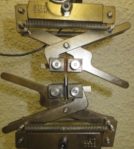
Fig. 12B
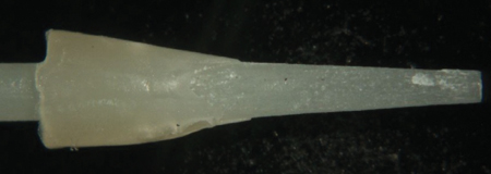
Fig. 12C
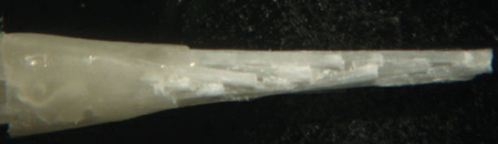
The retention of a plastically inserted coronal-root restoration on the root is thus increased by a factor of 1.6 in a configuration of a bundle of seven individual, ultrafine posts.
The debonding face seems different: The central posts detach with a dry sound, indicating the fracture of the adhesive interface remaining in the intrados of the canal. The multi-posts de-bond with a progressive noise for forces higher than 54%. These results can be attributed to the adhesive-post interfaces, which in the case of a machined post is 4.7mm2 and in the case of multi-posts of 17.0mm2.
Thus, an area ratio of 3.6 between the single taper (ST) post and the multi-posts indicates better retention of the multi-posts. In another study,19 the positive influence of multi-posts in the filling and retention of a coronal root restoration was investigated.
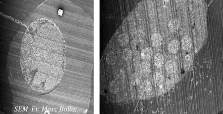
SEM sections confirm this increase in bonding interfaces (Fig. 13).10
Fig. 13
Multi-post placement protocol: The protocol for the placement of multi-posts detailed on the website (www.youtube.com/watch?v=o0QahGtFP0A) takes into account the previous analyses and the particularities of the bonding which is different on enamel and on dentin.
- Indication for multi-post coronal restoration.
The ideal core would be to ensure its own stability and resistance. The additional means of retention (pulpal or root canal depth anchorage) only aim to restore the tooth’s structural continuity while contributing to the root canal sealing. The devitalized tooth has 2 to 3 residual walls at least 1 mm thick and at least 1/3 of the coronal height. - Determination of the size of the multi-posts
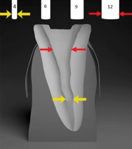
A radiological gauge (retro-alveolar) can be clipped onto the digital radio sensor. It will allow determining the number of multi-posts to obtain the best possible root canal anchorage. When the radiograph is taken, the gauge representing the multi-posts of 4, 6, 9, and 12 strands appears in superimposition on the tooth.
It allows you to select the number of strands needed (Fig. 14) determined by the conicity of the coronal zone of the canal: multi-post of 12 strands, 4 (yellow) to be pushed in contact with the apical plug, 8 (red) to be distributed on the periphery. - Preparation of the tooth
The tooth should be isolated from oral fluids by any useful means and thoroughly cleaned to promote adhesion and create a micro-mechanical retention that contributes strongly to the retention of individual cores.15 Tissues unsuitable for bonding residues of obturation products are removed mechanically (Gates or Largo drills, followed by cleaning with ultrasonic diamond inserts and micro-sanding).
- Selective etching of enamel with phosphoric acid – The 96% mineral enamel is not bonded like the 70% mineral, tubular-structured dentin. Therefore, avoid aggressive acid etching of dentin. Rinse the enamel thoroughly and dry it moderately with paper cones.
- Coating the enamel and dentin surfaces with adhesive – The structure of root dentin is 20% organic. It has a 10% aqueous phase, an obvious obstacle to bonding. The intra-canal surface must not be etched aggressively, and the adhesive system must be self-etching with a dual setting. This type of adhesive stabilizes the dentin sludge and facilitates its wetting and infiltration into the cavity walls. The etching agent exploits the acidity of certain monomers capable of simultaneously demineralizing and infiltrating calcified dental tissue.
Fig. 14
The use of these acidic primers should not be followed by rinsing, as the monomers they contain will secondarily contribute to the copolymerization with the filling composite. This etching can be activated by stimulating contact with a micro-brush by rubbing the surfaces for 20 seconds. Insert a paper cone while waiting for the restoration to be done.
- Securely impregnating the multi-posts with the filling composite19
The multi-posts are ready to use and require no additional preparation. They are packaged with a translucent impregnation sleeve that fits the tips of the usual small-diameter mixers (Fig. 15a). The coating of the micro-posts with the dual cure adhesion primer is not recommended: it would result in the micro-posts being bound together, preventing their future distribution in the canal and the coronal portion of the restoration.
The operator has the polymerization time indicated in the manufacturer’s instructions. When using self-etching systems (SE), it is essential to match the filling resin to the adhesive used. This composite type has an optimized fluidity to be injected without overflowing during implantation of multi-posts and the entire restoration. (Fig. 15b) It produces a tight seal and, by filling with nanohybrid zirconia particles, a grinding sensation identical to dentin. - Construction of the coronal-radicular restoration
Fig. 15A
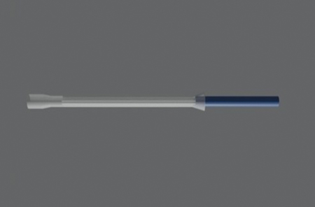
Fig. 15B
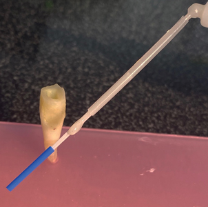
a) Filling the canal and inserting the multi-posts
The micro-mixing tip is disconnected from the impregnating sleeve, and the root canal is backfilled with a dual-cure filling composite adhesive. Do not hesitate to overfill (Fig. 16a). The multi-posts are inserted into the canal. It is unnecessary and not recommended to force the multi-posts into the canal, which would result in their subsequent distribution in all the available space. Light curing is not initiated at this stage (Figs. 16b & c).
Fig. 16A
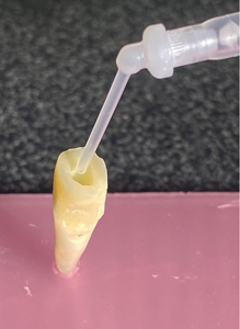
Fig. 16B
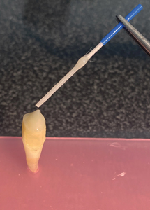
Fig. 16C
b) Harmonization of the reinforcements
The length of the micro-posts is adjusted exclusively with fine scissors (Fig. 17a) their small diameter allows the removal of the gripping sheath with a clean section and without grinding. The micro-posts are then freed (Fig. 17b), making it possible for them to use the available space.
With the help of a flat-tip probe (Fig. 7b), the necessary axial and peripheral distbution can be optimized, favouring the peripheral areas. Each micro-post can be moved to occupy the root canal if the filling composite has not polymerized. The filling composite will slow down the movement of the strands into the desired position. It is recommended that the central strands be pushed axially into contact with the apical plug as a priority. (Fig. 17c) Secondly, distribute the remaining strands towards the toothed periphery. (Fig. 17d)
Fig. 17ABCD
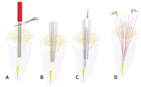
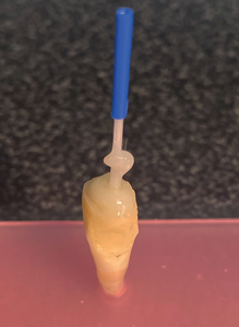
c) Core Build-up
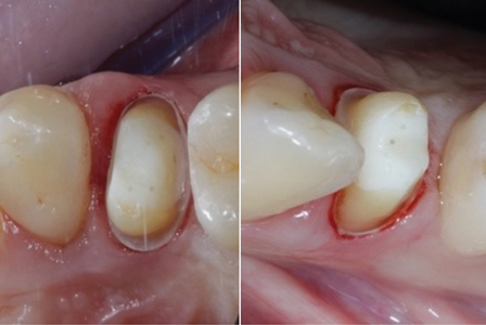
The core build-up is completed by filling the coronal portion with the same composite filler. (Figs. 18abc)
All the facets of the unit are then photo-polymerized. The isolation dam is removed, and the tooth is reshaped to receive a crown (Figs. 19ab)
Fig. 18ABC
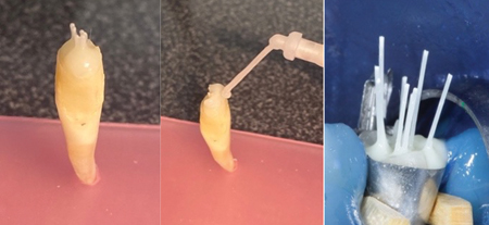
Fig. 19AB
Summary
- It is more effective to have the fibre reinforcements located in the corono-radicular peripheral areas subject to high tension.
- The contact area between the adhesive composite and the fibre reinforcement in a configuration with seven micro-posts is increased by 45% compared to a configuration using a 1.5 mm diameter master post.
- The retention of post and core on the root is increased by a factor of 1.6 in a 7 micro-post configuration.
- Reinforcing the peripheral area of the coronal stump with long fibres increases the coronal stump’s resistance to delamination and fracture.
- A larger possible number of 300-micron micro-posts well distributed throughout the structure is preferable to a single standardized master post.
This design of root-core restorations with plastic-inserted materials consists of a fibrous-architected material with a strong, continuous, overall reinforcement without unnecessary intrusion into the root dentin. In fact, this new organization of the fibrous posts involves the available root volume and a larger portion of the coronal stump, resulting in a more homogeneous, stronger assembly with improved intra-radicular retention.
Oral Health welcomes this original article.
Special Thanks to: Raphaël Richert, Engineer (école des mines), and Assistant DDS at the University of Lyon. Bernard Besson, DDS Grenoble and Alexandre Marin, DDS Grenoble.
References
- Reeh ES, Messer HH, Douglas WH. Reduction in tooth stiffness as a result of endodontic and restorative procedures. J Endod 1989; 15 (11): 512-516.
- Dietschi D, Duc O, Krejci I, Sadan A. Biomechanical consi- derations for the restoration of endodontically treated teeth: a systematic review of the literature–Part 1. Composition and micro- and macrostructure alterations. Quintessence Int 2007; 38 (9): 733-743.
- Clunet-Coste B, Maneuf B. Le concept Targis/Vectris, les composites à renforts de fibres: une alternative aux maté- riaux métalliques. Conception, fabrication et recul clinique. Information Dentaire 1998; 80 (32): 2347-2361.
- De Oliveira MA et al. Critical instrumentation area: influence of root canal anatomy on the endodontic preparation. Braz Dent J 2014; 25 (3): 232-236.
- H atta M et al. High volume individual fibre post versus low volume fibre post: the fracture load of the restored tooth. J Dent 2011; 39 (1): 65-71.
- Cheleux N. Reconstitution de la dent dépulpée par tenon fibré: les clés de la réussite. Clinic 2009; 30: 379-389.
- Dejou J, Laborde G. Comportement biomécanique de la dent dépulpée. Réal Clin 1990 ; 1 : 185-194.
- Berthelot JM., Matériaux composites. Comportement méca- nique et analyse des structures. Ed. Technique et documenta- tion. 1999.
- Dyer SR, Lassila LV, Jokinen M, Vallittu PK. Effect of fiber posi- tion and orientation on fracture load of fiber-reinforced compo- site. Dent Mater 2004; 20 (10): 947-955.
- Bolla M. Restaurer la dent dépulpée. Espace ID, Presse Edition Multimedia 2014.
- Akkayan B, Gülmez T. Resistance to fracture of endodontically treated teeth restored with different post systems. J Prosthet Dent 2002; 87 (4): 431-437.
- Kivanç BH et al. Fracture resistance of thin-walled roots res- tored with different post systems. Int Endod J 2009; 42 (11): 997-1003.
- Li Q, Xu B, Wang Y, Cai Y. Effects of auxiliary fiber posts on endodontically treated teeth with flared canals. Oper Dent 2011; 36 (4): 380-389.
- Giovani AR, Vansan LP, de Sousa Neto MD, Paulino SM. In vitro fracture resistance of glass-fiber and cast metal posts with different lengths. J Prosthet Dent 2009; 101 (3): 183-188.
- Pirani C et al. Does hybridization of intraradicular dentin really improve fiber post retention in endodontically treated teeth? J Endod 2005; 31 (12): 891-894.
- Lopes GC, Cardoso Pde C, Vieira LC, Baratieri LN. Microtensile bond strength to root canal vs pulp chamber dentin: effect of bonding strategies. J Adhes Dent 2004; 6 (2): 129-133.
- Haller B. Which self-etch bonding systems are suitable for which clinical indications? Quintessence Int 2013; 44 (9): 645-661.
- RIcherd R. Analyse biomécanique de la prémolaire délabrée : intérêt des éléments finis, Université Claude Bernard Lyon 1 U.f.r d’odontologie thèse n° 2020 lyo 1d06
- Naji Kharouf, Salvatore Sauro, Hamdi Jmal5 , Ammar Eid, Mohamed Karrout, Nadia Bahlouli,Youssef Haikel and Davide Mancino, Does Multi-Fiber-Reinforced Composite-Post Influence the Filling Ability and the Bond Strength in Root Canal? Bioengineering 2021, 8, 195
- S.Koubi, H.Tassery, JL Brouillet, Reconstitutions corono-radiculaires fibrées, qu’en est-t-il ? Département d’Odontologie Restauratrice Faculté de Marseille, L’INFORMATION DENTAIRE n° 25 – 18 juin 2008
- R.Richert, J.C. Maurin, M Ducret, Cyril VILLAT, PU-PH, Hospices Civils de Lyon Les micro-tenons, une reconstitution corono-radiculaire minimalement invasive, L’INFORMATION DENTAIRE nn°9/10 – mars 2022.
- R.Richert, P. Robinson,Maxime Ducret, Gilbet Vigule, JC Farges, Multi-Fiber-Reinforced Composites for the Coronoradicular Reconstruction of Premolar Teeth: A Finite Element Analysis, BioMed Research International, Volume 2018, Article ID 4302607
- G.T. Roccaa,∗, P. Sedlakovaa, C.M. Sarattia, R. Sedlacekb, L. Gregora,N. Rizcallaa, A.J. Feilzerc, I. Krejcia, Fatigue behavior of resin-modified monolithic CAD–CAM RNC crowns and endocrowns, 2016 The Academy of Dental Materials, Elseiver
About the Author

Dr. Bruno Clunet-Coste completed his DDS in 1971, and owns a private practice in Grenoble, France. He is a specialist in prosthodontics, parodontology and implantology. He has been working on Fiber Reinforced Composites since 198O. In collaboration with Dr. Bernard DURET, he has designed the first FRC system ever marketed in the world (dental fibre posts and frameworks) and still contributes to the technological innovations of the BCM society in France.