One of the primary goals of restoring anterior teeth is to provide the best possible aesthetic result. This includes shade (value, hue), proportions, and symmetry. One material option for restoring anterior teeth is composite; its benefits include reversibility, interim usage as a provisional, and eventual transition to porcelain. Any damage to the composite is easily repaired in a timely manner and is cost-effective to both the patient and dentist. Composite disadvantages including staining, leakage, and lack of long-term stability. Injectable composite techniques are well documented for their efficiency and functional predictability.1-4
Functional Goals
The functional impact of anterior teeth, both maxillary and mandibular, must be included in the primary restorative goals. Form does follow function, and restorative goals should respect the basic requirements of a stable occlusion.5
- Equal intensity contacts on all teeth while the joints are in centric relation.
- Disclusion of posterior teeth on working side.
- Disclusion of posterior teeth on non-working side.
- Disclusion of posterior teeth on protrusive guidance.
- Anterior guidance in harmony with the envelope of function.
The development of a stable occlusion recognizes the functional importance of anterior teeth. Anterior coupling (or guidance) protects the posterior teeth during functioning movements, providing the needed disclusion.6,7
Envelopes of Motion
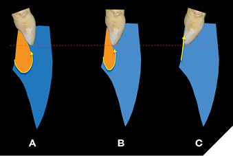
Stable occlusion can be clarified by examining the Envelope of Motion (EOM) and Envelope of Function (EOF). The Envelope of Motion is outlined by the path of the mandibular anterior teeth as the condyle moves within the eminence. The movements begin at centric relation, followed by rotation, then full translation, and then the condyle’s return to the Centric relation starting point centric relation (Fig. 1). The Envelope of Function resides primarily within the Envelope of Motion, (Fig. 2) limited by the lingual contours and incisal edges of the maxillary central incisors, and the leading edge of the mandibular central incisors. The EOF boundaries are established in 3 steps.
Fig. 1
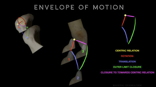
Fig. 2
- Patient slides mandible protrusively to create a smooth path of disclusion (in to out)
- Patient sits upright, leans forward, and opens/closes in a chewing motion (out to in)
- Phonetic test-patient counts “61 to 66”
This Envelope of Function is variable, depending on the position of the maxillary anterior teeth, as in Three Envelopes of Function with the maxillary incisal edge all in the same position (Fig. 2). As the maxillary anterior tooth axial position becomes more acute, the corresponding Envelope of Function becomes more restricted, a pattern observed in Class II Div 2 and/or excessive anterior wear patients. Patients with worn anterior dentition require the careful development of ideal form and function to achieve a stable occlusion.8
Case Description
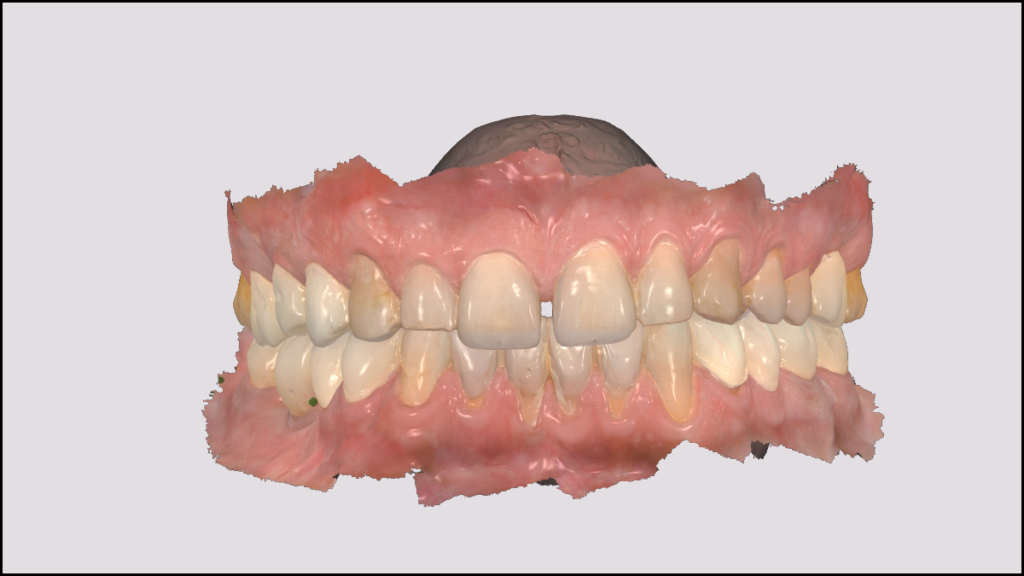
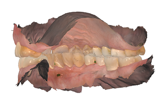
The 54-year-old male patient, whose initial motivation was a second opinion, presented with many signs of instability, including malocclusion. He reported that his previous dental treatment has worsened his occlusion, affecting his quality of life, including eating/chewing difficulties, muscle pain, and lack of quality sleep. His primary focus was functional improvement to better his overall quality of life. He preferred to phase treatment over time. A comprehensive examination was completed along with diagnostic records (Digital photography, digital scans, Centric Bite record, and facebow transfer). The result of the comprehensive examination revealed the following.
Fig. 3A
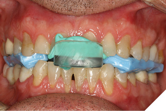
Fig. 3B
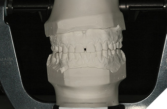
Fig. 4
TMJ
a. Crepitus on opening
b. Mandibular deviation to the right on closing
c. No tenderness to palpation on either side
d. No tension or tenderness on joint loading
Muscles of Mastication: Level of Tenderness during palpation
a. Right side: Mild- Temporalis; Moderate-Masseter, Deep Masseter, Lateral pterygoid; Severe-medial pterygoid, posterior neck
b. Left side: Mild-Digastric, Temporals, posterior neck, shoulder; Moderate-Masseter, Deep Masseter, medial & lateral pterygoid; Severe-none
Occlusion: Dental/Skeletal class I; overbite-3mm, overjet-2mm;
a. Right working interference 17,14, 44, 47; Left non-working-24, 34
b. Left working interference-24, 34; right non-working-17,14,44,47.
c. First point of contact in centric relation-Right canine, 13, 43 with an anterior left slide into Maximum intercuspation
Fig. 5
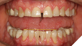
Fig. 6
Fig. 7
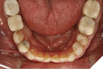
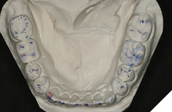
Dentition
a. Dental Implants at 16 (ceramic), 46 (provisional)
b. Multiple existing full coverage provisional crowns –37, 36, 44, 46, 47
c. Multiple existing large composite restorations-16, 14, 35, 34, 45
d. Periodontal health-generalized bleeding around provisional restorations, some 5mm probing around right posterior teeth.
e. Wear noted on upper and lower anterior teeth
The diagnostic models were mounted in centric relation on a semi adjustable Whipmix Mark 320 (Whip Mix, Louisville, KY) articulator using the facebow and centric bite record. The analysis revealed the following.
- Centric 1st points of contact(s) right canine (13/43) and lateral incisor (12/42), light contacts on maxillary bicuspids. No solid centric contacts on the molar teeth.
- Right working interferences lateral incisor (12/42) with some canine guidance (13/43).
- Left canine guidance (23/33), non-working interferences nonexistent.
- Protrusive contacts being dominated by right lateral incisor (12/42).
- Maxillary central incisors exhibit compromised length to width ratios.
- Mandibular central incisal edges worn, inadequate incisal plane.
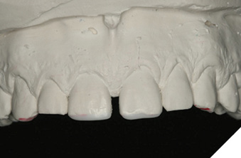
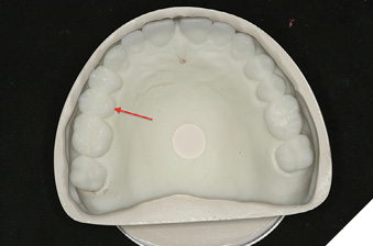
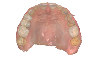
The process of achieving occlusal stability ideally begins with the visualization of the maxillary and mandibular incisal edge position, both horizontally and vertically. Teeth 11 and 21 are worn and the gingival margins are not symmetrical. As a result, tooth 11 appears to be more” square” in shape when compared to 21 (Fig. 8). Both maxillary and mandibular teeth can be reshaped to create an ideal incisal plane that is complementary to the entire arch form. The current mandibular arch exhibits central incisors that are rotated and other anterior teeth appearing bulky (Fig. 9). Modifications include reshaping of 33 (Figs. 10, 10A) and adding wax to the remaining central incisors (Fig. 11) to increase their length, producing a stable incisal edge plane (Fig. 12) that will serve as the starting point in the development of the ideal occlusion. The same process is followed for the maxillary anterior teeth. The centrals were modified to create a more ideal appearance (Figs. 13, 14). Since function was the patient’s primary focus, aesthetics (including diastema closure) were not addressed at this stage as per patient’s request.
Fig. 8
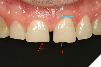
Fig. 9
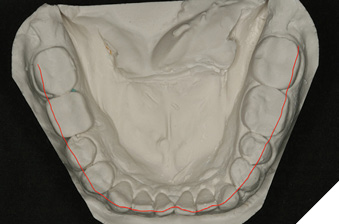
Fig. 10A
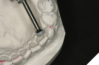
Fig. 10B
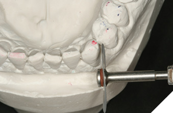
Fig. 11
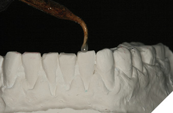
Fig. 12
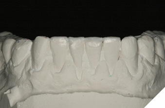
Fig. 13
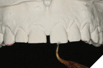
Fig. 14
Once the incisal edges of the mandibular and maxillary anterior teeth have been modified, the models are returned to the articulator to begin the development of a stable occlusion. For this patient, the first point of contact changed to the maxillary central incisors (Fig. 15). As more teeth occlude, the choice is to continue equilibration or to bring the remaining teeth into contact. Minimal additive equilibration (Fig. 16) is completed on several posteriors to establish ideal occlusal contacts and a stable occlusion (Figs. 17A and 17B). The treatment plan based on the diagnostic models included injectable composite to restore the anterior tooth functionality and posterior provisional restorations to establish occlusal stability.
Fig. 15
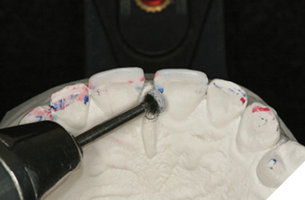
Fig. 16
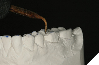
Fig. 17A
Fig. 17B
The following treatment was proposed.
- Composite veneers 32, 31, 41 and 42.
- Composite crowns 11 and 21.
- Provisional individual, non-splinted crowns 37-34, 44-47.
- Full mouth equilibration.
- Fabrication of nighttime retainers after finalization of occlusion.
- Conversion of provisional crowns to permanent over time (as per the patient).
This information (including digital scans and digital photography) was sent to the laboratory (CMR Dental Laboratory, Idaho Falls, ID) for digital finalization and production. Precise dentist-laboratory communication is essential. The completed analog diagnostic models (along with all diagnostic photos) are used as a reference. The laboratory scanned the models and digitally mounted them to create the ideal contours and occlusion. The prescription also includes instructions for the fabrication of digital wax up models in stages, allowing the occlusal correction in the same sequence as was performed on the diagnostic models. The staged models permit the dentist to work efficiently, without losing any stable reference points during the process.
The laboratory prescription included:
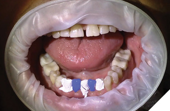
- Mandibular anterior (32-42) + silicone injectable matrix (Figs. 18A, 18B and 18C).
- Mandibular posteriors (37,35, 45, 47) + putty provisional matrix (Figs. 21 and 22A).
- Mandibular posteriors (36,34, 44, 46) + putty provisional matrix (Fig. 22B).
- Maxillary anterior (11, 21) + silicone injectable matrix (Figs. 19 and 20C).
- Maxillary posteriors (16, 14, and 26) + putty provisional matrix (Figs. 23A and 23B).
- Maxillary posteriors (15) + putty provisional matrix (Fig. 23C).
Fig. 18A
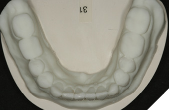
Fig. 18B
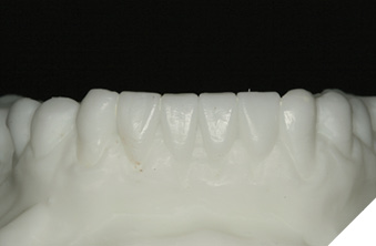
Fig. 18C
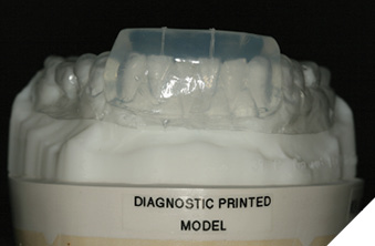
Fig. 19
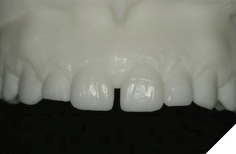
Fig. 20
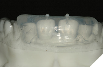
Fig. 21
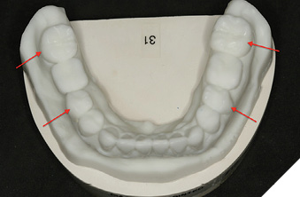
Fig. 22A
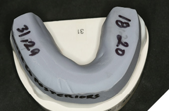
Fig. 22B
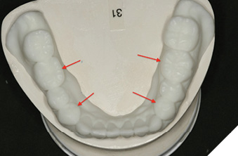
Fig. 23A
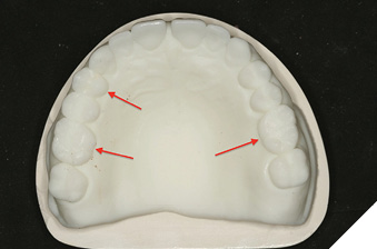
Fig. 23B
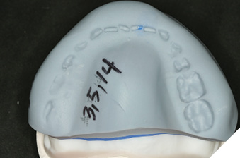
Fig. 23C
Clinical Procedure
The mandibular incisors (32-42) were restored using injectable composite (G-Aenial Universal Injectable, GC America, Alsip, IL). After OptraGate (Ivoclar Vivadent, Buffalo, NY) is olation, teeth 34, 41, and 43 were protected with Teflon tape. Facial surfaces on 31 and 42 were slightly modified, followed by acid etching (35% Phosphoric Acid-Ultra Etch Ultradent, South Jordan, UT) for 20 seconds (Fig. 24A), and rinsed for 5 seconds.
Fig. 24A
Multiple coats of Excite F bonding agent (Ivoclar Vivadent, Buffalo, NY) were applied and air dried (Fig. 24B). The Silicone injectable matrix was placed over the lower arch, the injectable composite tip placed into the vertical slot, and material was injected into the matrix (Fig. 24C). After a 20 second light cure, flash was removed. The remaining incisors (32 and 41) were restored in the exact manner (Fig. 25A). The restorations were finished and smoothed with Gateway Flex fine diamond polishing strips (Brasseler USA, Savanah, GA) (Fig. 27B). Then the maxillary central incisors were similarly prepared and finished (Figs. 26 and 27A).
Fig. 24B
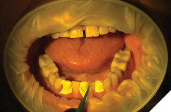
Fig. 24C
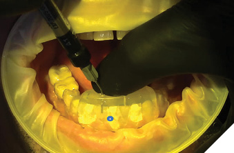
Fig. 25A
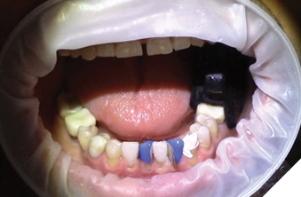
Fig. 25B
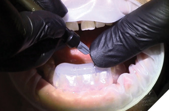
Fig. 26
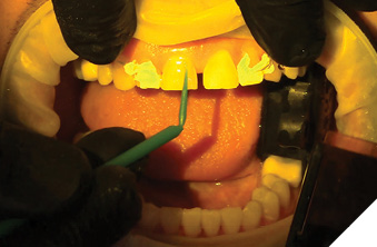
Fig. 27A
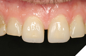
Fig. 27B
Continuing the restorative sequence, 47, 45, 35 and 37 were prepared. Utilizing the provisional putty matrix that preserved the original teeth shapes of 34, 36, 44 and 46, the matrix was predictably seated to fabricate the provisional restorations (Fig. 28A). The preparation and restoration of 34, 36, 44 and 46 utilized the same process to achieve the completed mandibular posterior provisional restorations (Fig. 28B).
Fig. 28A
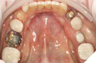
Fig. 28B
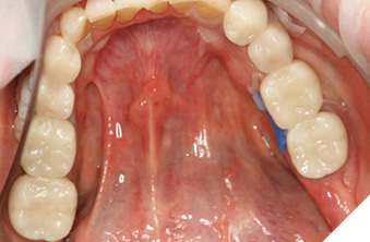
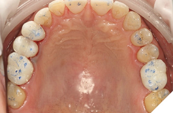
The final step was to fabricate the maxillary posterior provisional restorations. Teeth 16, 14 and 26 (porcelain implant crown) were prepared (Fig. 29A) and using the putty matrix, provisional restorations were completed (Fig. 29B) with Visalys Temp A1 (Kettenbach USA, Huntington Beach, CA). Stability, which depends on rigidity, improves the seating of the putty matrix. When the opposing dentition is imprinted on the verso side of the matrix, the patient can bite into the matrix with equal pressure to enhance the stability while the material is fully cured (Fig. 29C). After completion of the maxillary restorations, (Fig. 30) all provisional crowns were trimmed, polished, and cemented (Rely X Temp NE, 3M USA, St. Paul, MN).
Fig. 29A
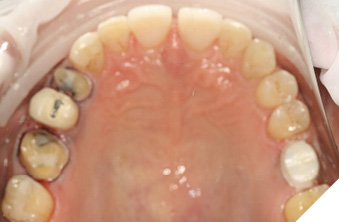
Fig. 29B
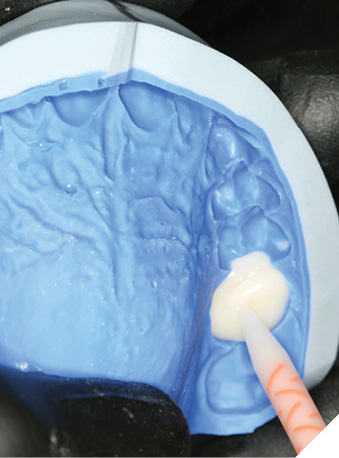
Fig. 29C
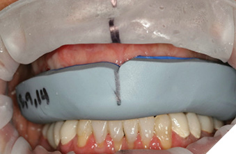
Fig. 30
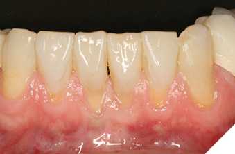
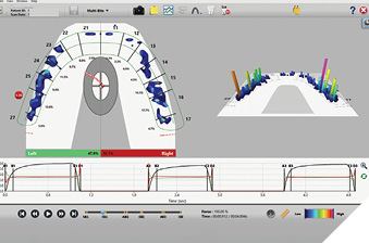
Finally, the restorations were equilibrated with the patient TMJs in centric relation. Heavy contacts were corrected by reshaping the restorations (Figs. 31A and 31B). Because the laboratory predictably created the best occlusion possible from the diagnostic models, (Figs. 32A and 32B) little adjustment was needed. The anterior guidance and the envelope of function are the focal points of the equilibration. The anterior guidance from centric relation into excursive movements should be smooth and effortless (Fig. 32C). Upon completion of the equilibration, the patient should return for a follow up visit to fine tuning the occlusion within a week or so. Another reason for this follow-up is to find out how the muscle reprogramming has affected the occlusion and what the patient is experiencing. A T Scan image of the maxillary arch (Tekscan Inc., Norwood, MA) of the final occlusion illustrates balanced forces (48% left, 52% right) with the occlusal forces shared by all teeth (Fig. 33).
Fig. 31A
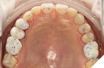
Fig. 31B
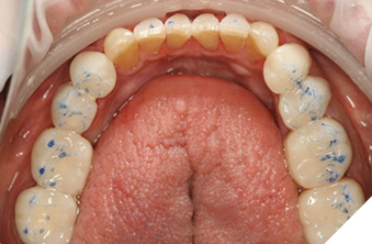
Fig. 32A
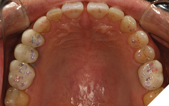
Fig. 32B
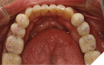
Fig. 32C
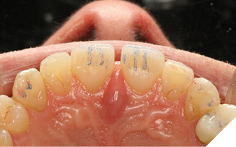
Fig. 33
Nighttime retainers were the final step to protect the provisional restorations. Digital scans were taken after the occlusion was verified (Figs. 35A and 35B).
Fig. 34
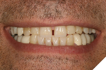
Fig. 35A
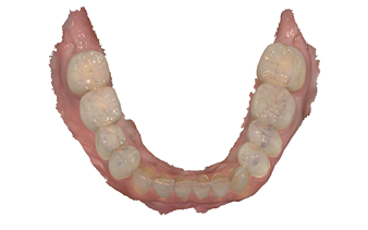
Fig. 35B
Conclusion
It is essential for the restorative dentist to have complete control in all phases of treatment, ensuring that the outcome is predictable and gives the patient great satisfaction. Treatments fail not in the restorative phase but in the planning phase. Failing to plan is planning to fail.9 Thus, the clinician must invest time into the planning phase(s). Composite materials are an excellent choice where patients are not ready to commit to final restorations, need to phase treatments over time, or need the development of occlusal stability due to existing malocclusion. A corollary of this leadership skill is effective communication with all team members, including the master digital designer (Brit Schiner-CMR Dental Laboratory, Idaho Falls, ID). In the clinical case presented, the initial occlusal analysis was the most important element in securing a positive outcome. This resulting treatment plan was logical and systematic. The analysis and the treatment plan allow the clinician, laboratory and the patient to communicate and work together towards a superior outcome that looks natural and functions well (Figs. 34, 36A-36D).
 Fig. 36A
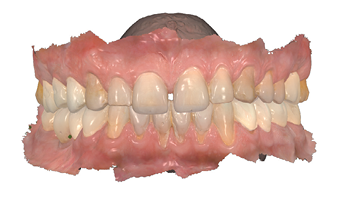
Fig. 36B
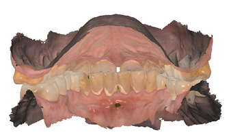
Fig. 36C
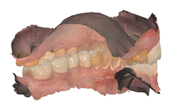
Fig. 36D
Oral Health welcomes this original article.
References
- Geštakovski, D. (2021). The injectable composite resin technique: biocopy of a natural tooth – advantages of digital planning. The International Journal of Esthetic Dentistry, 16(3).
- Ypei Gia, N. R., Sampaio, C. S., Higashi, C., Sakamoto, A., & Hirata, R. (2021). The injectable resin composite restorative technique: A case report. Journal of Esthetic and Restorative Dentistry, 33(3). https://doi.org/10.1111/jerd.12650
- Geštakovski, D. (2019). The injectable composite resin technique: minimally invasive reconstruction of esthetics and function. Clinical case report with 2-year follow-up. Quintessence International (Berlin, Germany : 1985), 50(9). https://doi.org/10.3290/j.qi.a43089
- Cortés-Bretón Brinkmann, J., Albanchez-González, M. I., Lobato Peña, D. M., García Gil, I., Suárez García, M. J., & Peláez Rico, J. (2020). Improvement of aesthetics in a patient with tetracycline stains using the injectable composite resin technique: case report with 24-month follow-up. British Dental Journal, 229(12). https://doi.org/10.1038/s41415-020-2405-x
- Dawson, P. E. (2007). Functional Occlusion : From TMJ to Smile Design. Mosby Elsevier.
- Broderson, S. P. (1978). Anterior guidance-The key to successful occlusal treatment. Journal of Prosthetic Dentistry, 39(4), 396–400.
- Cohen, R. (1956). The relationship of anterior guidance to condylar guidance in mandibular movement. Journal of Prosthetic Dentistry, 6(6), 758–767.
- Khanna, N. (2020). Functional Aesthetic Dentistry. In Functional Aesthetic Dentistry. https://doi.org/10.1007/978-3-030-39115-7
- Dawson, P.E. (1989) Evaluation, Diagnosis, and Treatment of Occlusal Problems. 2nd Edition, CV Mosby, St. Louis.
About the Author

Dr. Khanna graduated from University of Toronto, with post-grad (Detroit-Mercy) followed by a GPR (University of Rochester). He is a Senior Faculty Member, Dawson Academy. Dr. Khanna, author of Functional Aesthetic Dentistry: How to Achieve Predictable Aesthetic Results Using Principles of a Stable Occlusion (Springer Nature), lectures nationally and internationally. He maintains a practice dedicated to excellence in comprehensive restorative and aesthetic dentistry in Geneva, Illinois