Edentulism in the posterior maxillary region presents a challenging scenario for dental implant rehabilitation due to vertical ridge dimension bone loss and the close proximity to the floor of the maxillary sinus. In addition, alveolar ridge width loss and thinning of mucosa is a common clinical scenario in areas of long term tooth loss. To address these challenges, a combination of surgical techniques are often required to augment these sites prior to the optimal placement of the dental implants. This case report outlines a comprehensive treatment plan for the rehabilitation of three missing teeth with a combination of surgical and prosthetic techniques to achieve form, function and esthetics.
Case Presentation
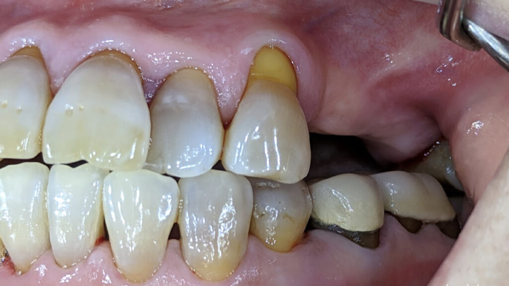
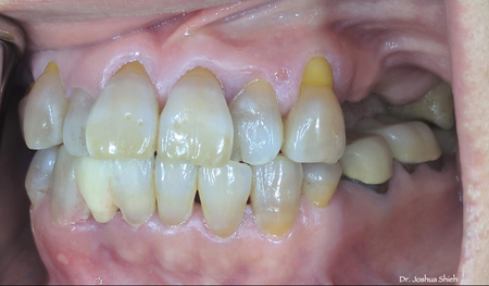
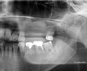
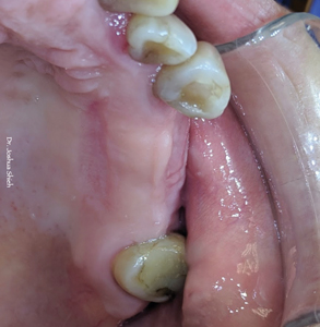
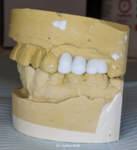
A 50 year young female, ASA 1, was referred for implant rehabilitation with three missing teeth in the left posterior maxillary region (#24, #25, and #26) (Fig 1). The patient had a chief complaint of “I am unable to chew my food on this side of my mouth” with a dental history of extracting teeth from a failed bridge many years ago.
Fig. 1
On dental history taking (collaborated with the referring dentist), she had 2 teeth that were root canal treated and were supporting a 3 unit fixed PFM bridge. The bridge had failed due to secondary decay causing the abutment for the #24 non restorable and a vertically fractured #26. Her #25 was missing for over 10+ years.
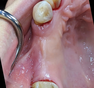
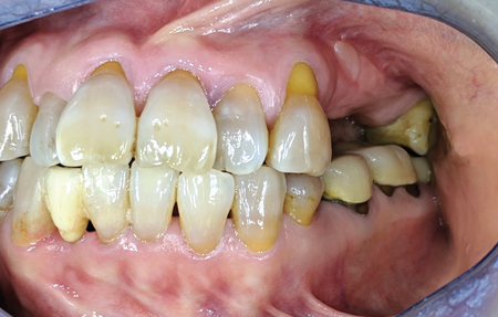
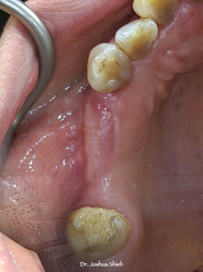
The patient is a bruxer and wears a night guard for the last 2 years. During the clinical examination, a few observations were made in the #25, #26 region (Fig 2).
Fig. 2

- Inadequate alveolar ridge width,
- Minimal attached gingiva and keratinized gingiva with a shallow vestibular depth, and
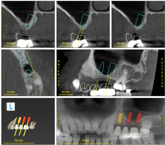
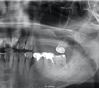
- Limited inter-occlusal restorative space (as seen in Fig 1). Radiographic evaluation shows inadequate vertical alveolar ridge height in the #25 and #26 region (Fig 3). Cone-beam computed tomography (CBCT) imaging confirmed the limited alveolar ridge dimensions with a clear maxillary sinus (Fig 4). With less than 2mm crestal bone – a direct sinus graft was planned (Fig 4a).
Fig 3
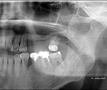
Fig. 4
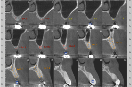
Fig. 4A
The patient expressed a strong desire for a functional and esthetic restoration.
All surgical procedures were performed under local anaesthesia only.
Surgical phase
Step 1: Direct Sinus Lift
A lateral window sinus procedure (Fig 5) was planned an executed to increase the height and available bone volume in the 25-26 region. This surgical procedure involved the careful preparation of a bony window (Fig 6) along the lateral sinus wall and gentle elevation of the sinus membrane with addition of particulate allograft biomaterial into the sinus space (Fig 7 and 7a).
Fig. 5
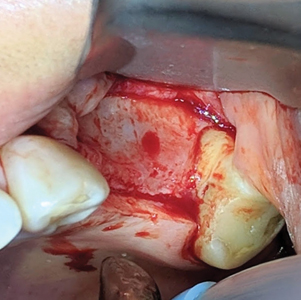
Fig. 6
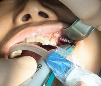
Fig. 7
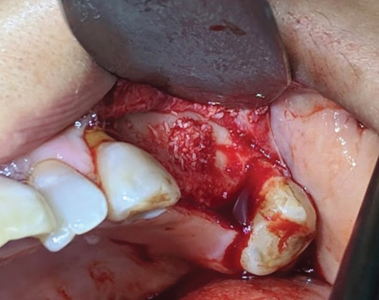
Fig. 7A
Acellular Dermal Matrix (ADM):
To improve tissue thickness and its biotype, an acellular dermal matrix was utilized. ADM was placed over the collagen membrane on the grafted site to provide adequate soft tissue support and thickness (Fig 8). Post op follow ups were performed at 2 weeks and 4months (Fig 9 and 9a) with no surgical complications.
Fig. 8
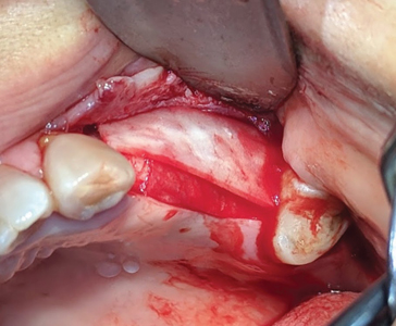
Fig. 9

Fig. 9A
Step 2:
At 4 months, the second stage of surgery was planned and executed. Minimal attached gingiva and a positive frenal pull (Fig 9a) had to be managed with a split thickness flap and use of a free autogenous gingival graft.
Free Gingival Graft:
First step in this surgical procedure is to move the mucogingival junction more apically with a split thickness flap (Fig 10). This incision also relieves the soft tissue tension from the buccal frenum over the 25 region. A free gingival graft was harvested from the palate (Fig 11) and transplanted to the area surrounding the future implant restoration sites (Fig 12). Post surgery follow up was done at 4 weeks with uneventful healing (Fig 13 and 13a).
Fig. 10

Fig. 11

Fig. 12

Fig. 13
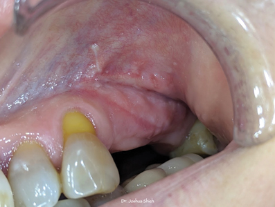
Fig. 13A
This graft was crucial for increasing the volume of attached / keratinized gingiva to provide a stable soft tissue environment around the implants and its restorations (Fig 14 and 14a).
Fig. 14

Fig. 14A
Step 3:
Six months post sinus graft procedure, a panoramic was taken (Fig 15).
Fig. 15
Bone remodelling was optimal and adequate vertical ridge height was now available for all 3 implant sites.
An alginate impression was made to fabricate study models for the lab to anatomically wax up the 3 missing teeth in ideal occlusal form and function (Fig 16 and 16a).
Fig. 16
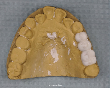
Fig. 16A
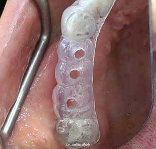
Using the waxed up model, an in house suck down essix type appliance (Fig 17) was fabricated for the initial pilot hole osteotomy for the ideal position of the future implant restorations (Fig 18).
Fig. 17
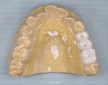
Fig. 18
Implant placement with simultaneous GBR:
After the required local anaesthetic, a full thickness flap was elevated exposing the underlying alveolar ridge (Fig 19). Using the essix appliance, initial pilot osteotomies where prepared with a 2.2mm dia drill at 7mm depth, guide pins (Fig 20) were placed and a radiograph was taken (Fig 21). After the final osteotomies were completed, prior to the placement of the implant fixtures, decortication (Fig 23) of the buccal wall was performed using a small round carbide of 1.0mm dia at 2000 rpm and copious sterile saline irrigation. Implant fixture dimensions of 3.5 x10 for the 24 site, a 4.0 x 10 for the 25 site and 4.5 x 10 for the 26 site were placed all at above 30ncm of insertion torque (Fig 22). Post insertion radiographs were taken and parallel positioning of the implants were confirmed (Fig 24). The buccal bone was additionally augmented with a mix of cortico-cancellous allograft and bovine derived xenografts (Fig 25) and layered with collagen membrane that was secured with 5-0 sutures (Fig 26). Adequate tissue release was performed to achieve tension free primary closure (Fig 27). Post op follow ups were done at 2 weeks and 4months, healing was uneventful (Fig 28).
Fig. 19
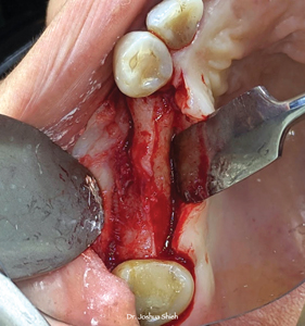
Fig. 20

Fig. 21

Fig. 22
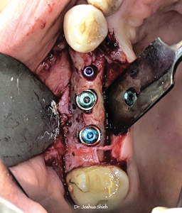
Fig. 23
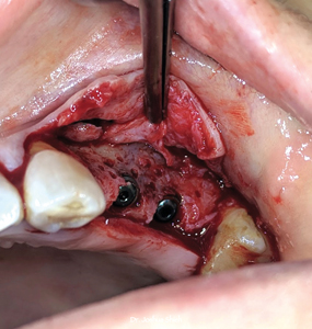
Fig. 24

Fig. 25
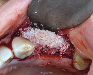
Fig. 26
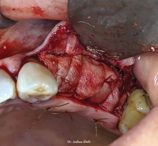
Fig. 27
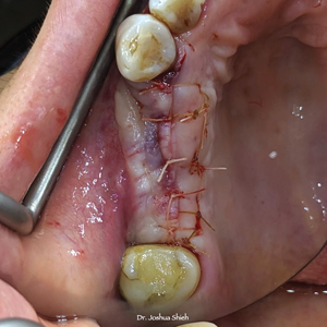
Fig. 28
Step 4:
Patient was advised to see the hygienist after the 4 month follow up and was then called in for the final surgical procedure, the placement of the healing abutments. A conservative mucoperiosteal flap was elevated to expose the cover screws, positive gain in bone volume was noticed along the buccal wall (Fig 29). Using a Lucas curette, the bone covering the cover screws were removed, well irrigated with sterile saline and the cover screws were replaced with appropriate sized healing abutments, periodical radiograph was taken to confirm fully seated healing abutments (Fig 30).
Fig. 29
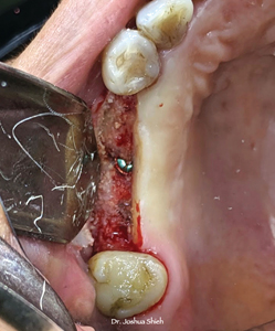
Fig. 30
The soft tissue was then put back meticulously around the healing abutments following the Palacci Technique (Fig 31). Uneventful healing was observed during the 2 week (Fig 32) and 2 month follow ups (Fig 33).
Fig. 31

Fig. 32
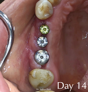
Fig. 33

Prosthetic Phase
After 2 months of soft tissue maturation (Fig 34), open tray impression copings (Fig 35) were placed and hand torqued (Fig 36). Periapical radiographs were taken to verify complete seating of the impression posts (Fig 37). A rigid PVS heavy and light body impression material (Fig 38) was used for the pick up impression technique (Fig 39). The patient had intrinsic staining of teeth from pharmacological derivatives and shades for the base was done chair-side with multiple shade tabs from 3D master shade guide (Fig 40) and she was also requested to visit the dental lab for custom shade mapping and visualization by the master technician – Mike Callaghan RDT.
Fig. 34

Fig. 35
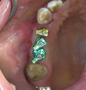
Fig. 36

Fig. 37
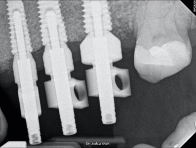
Fig. 38
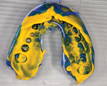
Fig. 39

Fig. 40

A 3 unit PFM non precious splinted restoration with non hexed abutments was designed and fabricated (Fig 41).
Fig. 41
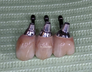
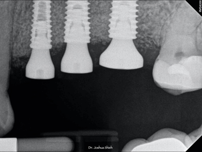
This restoration was inserted by placing the screws in a sequential manner at 3 turns per implant fixture until fully and passively seated by hand torque only (Fig 42). A periapical radiograph (Fig 43) was taken to confirm all 3 internal connections were fully seated, after which all three prosthetic screws were final torqued at 30Ncm. Proximal and occlusal contacts were verified and adjusted. The screw access holes were sealed with teflon tape and composite resin material. Custom composite stains were used on the occlusal screw access holes to give the appearance of stained grooves and fissures (Fig 44).
Fig. 42
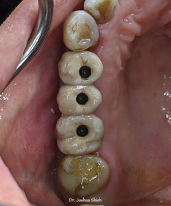
Fig. 43
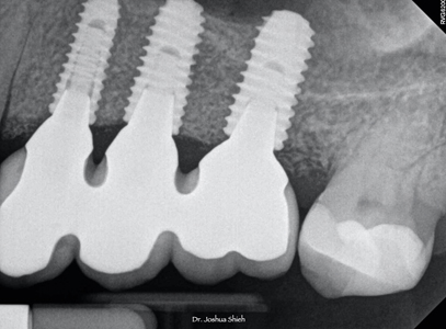
Fig. 44

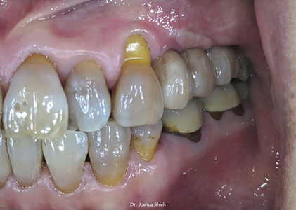
This multiple implant restoration was not only restored to full form and function but also achieved natural esthetics with a harmonious occlusion (Fig 45).
Fig. 45
Discussion
The patient experienced successful osseointegration of the three dental implants, and follow-ups demonstrated stable and healthy peri-implant tissues. The patient reported improved function, esthetics, and overall satisfaction with the final outcome.
The presented case underscores the importance of a comprehensive approach when rehabilitating multiple missing teeth in the posterior maxillary region.
This young lady was an ideal case depiction of a philosophical mindset1 with no contributory medical conditions, allergies or health related issues that would adversely effect the planned surgical procedures. Her primary concern was being unable to eat and mentioned during consult visits to achieving close to ideal form, function and optimal esthetics. Given her pre-surgical scenario, with alveolar ridge height of less than 2mm, a staged direct sinus graft utilizing the lateral window approach was performed. This procedure is the most common surgical intervention for increasing alveolar bone height prior to the placement of endosseous dental implants in the posterior maxilla. The survival rate of implants placed in sinuses augmented with the lateral window technique varied between 61.7% and 100%, with an average survival rate of 91.8%. Implants placed in sinuses augmented with particulate grafts show a higher survival rate than those placed in sinuses augmented with block grafts.2
Thin biotype characterizes thin gingival tissues. They are almost translucent and delicate with minimal zone of attached gingiva. Such tissues are highly accentuated suggesting the presence of thin or minimal bone. Evidence suggests that thin gingiva is less resistant to insults that are inflammatory or surgical in nature and more predisposed to tissue recession. It is for this reason that an ACDM was placed during the sinus graft procedure to help improve the tissue biotype prior to the next stage of soft tissue management. Thick gingival tissue characterizes thick biotype and is generally related with good periodontal health. It is dense in appearance and has sufficient zone of attached gingiva. Ample evidence indicates that thick tissues withstand trauma and subsequent recession, enable manipulation of tissue, encourage creeping attachment, enhance esthetics of implants, exhibit less clinical inflammation and also provide predictable surgical outcomes.3,4
Prosthetically driven implant surgery has become the standard of care to improve long-term functional and esthetic outcomes. Therefore, implant position and angulation are planned according to the available bone, anatomical structures, and the requirements of the future prosthetic superstructure. The use of data from cone-beam computed tomography scans has substantially improved the three-dimensional understanding of anatomical structures, and virtual planning of the ideal implant position.5 Various requirements, such as the desired inter-implant distance, implant depth and other aspects, have made implant planning an important tool when aiming for optimal treatment success. Wax-up of the missing teeth assists the surgeon to achieve a “top-down” planning considering the future prosthetic restoration in relation to available tissues.6 The edentulous space with limited restorative interocclusal space was waxed up prior to the implant placement and the use of an in-house essix template assisted in the optimal positioning of the 3 implants.
As clinicians, the predictability of achieving the desired outcome should play a decisive role in choosing the procedure and material. The detection of a vestibular (facial/buccal) bone defect at the future implant site during the planning stage is a common finding. Research has shown that bone resorption following the tooth extraction is more significant on the vestibular than on the lingual aspect, and even the elevation of a mucoperiosteal flap can impact adjacent teeth, depending on the location.7 Depending on the size and morphology of the defect, it can be left without grafting, grafted simultaneously with implant placement, or a two-stage surgery may be needed (ridge augmentation followed by implant placement). Additional correction with soft-tissue grafts may be necessary in more severe cases.8 This is especially true if the implant is placed in an optimal, prosthetically driven, three-dimensional position. From a functional point of view, a minimal (1–2 mm) exposure should neither affect osseointegration nor short-term implant health.9 Since the long-term loss of the newly grafted bone is expected, with average ridge resorption of 1.13 mm reported after grafting along the buccal ridge healing for at least 6 months, slight over-engineering may be recommended in some cases. It is worth noting that bone resorption after GBR can vary based on the patient’s individual phenotype dimensions, as observed in a study comparing the healthy contra-lateral site, This highlights the importance of considering over-engineering during GBR.10 After an adequate 4 months of healing time, the submerged implants were then exposed for the placement of the appropriately sized healing abutments with a soft tissue technique described as semilunar bevel incisions made to recreate a scalloped shape similar to that of tissues around natural teeth.11
The casts obtained from open-tray impression technique were more accurate as compared with the closed-tray technique. The accuracy of the multiple implant impression is influenced by the type of impression material used which ultimately leads to an accurate cast on which precisely fitting prosthesis is fabricated.12
Splinted screw-retained restorations are generally designed with non-engaging connections to avoid interference during insertion.13 Connections with long internal parallel engaging areas are much less tolerant to implant deviation compared to those with short conical connections.14 Conical connections have an internal flare of variable degrees. This allows a multiunit splinted restoration to be inserted and removed without interference even when implants are slightly divergent. When non-engaging abutments are used, the acceptable angle of divergence between 2 adjacent implants is the sum of the internal flare angles on either side of both implants.15
Due to limited restorative space, patient being an active bruxer, we decided to splint the 3 implant restorations. Quantitative analysis of all studies showed statistically significant higher survival rates for splinted restorations than for nonsplinted restorations.16
Conclusion
This case report highlights the successful surgical and prosthetic rehabilitation of three missing teeth in the posterior maxillary region using a combination of surgical techniques, including direct sinus lift, acellular dermal matrix, and free gingival grafts. The integration of these approaches led to increased alveolar bone availability, improved tissue thickness, attached/keratinized gingiva, and stable implant-supported prostheses, ultimately achieving a favorable functional and esthetic outcome for the patient. This case emphasizes the importance of a multidisciplinary approach to address complex dental rehabilitation cases effectively.
Oral Health welcomes this original article.
References
- 1House, M. M. Studies in prosthesis. J Am Dent Assoc 1931. 18:827–852.
- Stephen S Wallace, Stuart J Froum. Effect of maxillary sinus augmentation on the survival of endosseous dental implants. A systematic review. Ann Periodontol 2003 Dec;8(1):328-43
- Nagaraj KR, Savadi RC, Savadi AR, Prashanth Reddy GT, Srilakshmi J, Dayalan M, et al. Gingival biotype – Prosthodontic perspective. J Indian Prosthodont Soc 2010;10:27-30
- Chung DM, Oh TJ, Shotwell JL, Misch CE, Wang HL. Significance of keratinized mucosa in maintenance of dental implants with different surfaces. J Periodontol 2006;77:1410-20.
- Federico Brugnami , Cristiano Caleffi. Prosthetically driven implant placement. How to achieve the appropriate implant site development. Keio J Med 2005 Dec;54(4):172-8
- Laszlo Parkanyi, Frank Schwarz, Anton Sculean. Reducing errors in guided implant surgery to optimize treatment outcomes. Periodontology 2000, 01 February 2022
- Saleh MHA, Couso-Queiruga E, Ravida A, et al. Impact of the periodontal phenotype in premolar and molar sites on bone loss following full-thickness mucoperiosteal flap: a 1-year prospective clinical trial. J Periodontol. 2022; 93(7): 966-976.
- Chiapasco M, Casentini P. Horizontal bone-augmentation procedures in implant dentistry: prosthetically guided regeneration. Periodontol. 2018; 77(1): 213-240.
- Bouckaert E, De Bruyckere T, Eghbali A, Younes F, Wessels R, Cosyn J. A randomized controlled trial comparing guided bone regeneration to connective tissue graft to re-establish buccal convexity at dental implant sites: three-year results. Clin Oral Implants Res. 2022; 33(5): 461-471.
- Elnayef B, Porta C, Suarez-Lopez Del Amo F, Mordini L, Gargallo-Albiol J, Hernandez-Alfaro F. The fate of lateral ridge augmentation: a systematic review and meta-analysis. Int J Oral Maxillofac Implants. 2018; 33(3): 622-635.
- Patrick Palacci and Hessam Nowzari. Soft tissue enhancements around dental implants. Periodontology 2000, Vol. 47, 2008, 113–132
- Harpreet Saini, Shasikala Jain. Evaluating the Effect of Different Impression Techniques and Splinting Methods on the Dimensional Accuracy of Multiple Implant Impressions: An in vitro Study. J Contemp Dent Pract 2018, Aug 1, 1;19(8):1005-1012
- AlHelal A, Kattadiyil MT, AlBader B, Clark JL. A protocol for screw-retrievable, cement-retained, implant-supported fixed partial dentures. Int J Prosthodont. 2017;30:577–80.
- Binon PP. The effect of implant/abutment hexagonal misfit on screw joint stability. Int J Prosthodont. 1996;9:149–60.
- Choi JH, Lim YJ, Yim SH, Kim CW. Evaluation of the accuracy of implant-level impression techniques for internal-connection implant prostheses in parallel and divergent models. Int J Oral Maxillofac Implants. 2007;22:761–8.
- Victor Dsouza Batista, Fellipo Verri. Should the restoration of adjacent implants be splinted or nonsplinted? A systematic review and meta-analysis. J Prosthet Dent 2019, Jan; 121(1):14-51.
About the Author

Dr. Joshua Shieh is a third generation clinician and has been practising general dentistry in Ontario since 2015. Over the last eight years, he has earned his Diplomate of the American Board of Oral Implantology, Fellow of the International Congress of Oral Implantology and Fellow of the Academy of General Dentistry. A travelling surgical associate in the GTA with special interests in wisdom teeth, hard and soft tissue regeneration around teeth / implants, surgical implant placements and full arch implant rehabilitations. The author can be reached out via email: drjoshuashieh@gmail.com